22
- FORM NO. 56043096 - Captor
™
4300B, 4800B
SWEEPING SYSTEM
MAIN BROOM MOTOR BELT REMOVAL
1
Remove the left side scrub brush skirt assembly and then lower the scrub deck.
2
Drain the Vacuum recovery tank and remove the tank from the machine. Then disconnect the battery.
3
Follow the
Main Broom Drive Belt Replacement
instructions in this manual section. They must be removed first to access the inner broom
motor belts.
4
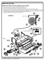
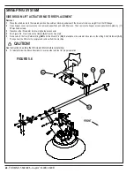
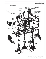
See Figure 5.2. Remove the (4) Screws
(S)
that fasten the Rear Belt Guard
(T)
.
5
From underneath the machine loosen the belt tensioner adjustment Lock Nut
(W)
and also locate and loosen the (4) broom motor mounting
Screws
(H)
.
6
Next lower the broom motor by turning the adjustment Screw
(X)
counter clockwise (CCW) to shorten the distance between the (2) Pulleys
(R
and
I)
. Then remove the (2) broom motor Belts
(Y)
.
MAIN BROOM MOTOR BELT INSTALLATION AND TENSIONING ADJUSTMENT
1
It is important to replace both broom motor Belts
(Y)
as a matched set so that the belt tension is the same for both.
2
Roll two new belts onto the Pulleys
(R
&
I)
. Then turn the adjustment Screw
(X)
clockwise (CW) to increase the belt tension to 1/8” deflection
at mid point and tighten the Lock Nut
(W)
.
3
Reinstall the Rear Belt Guard
(T)
.
4
Follow the instructions in this manual section to reinstall and tension the main broom Belt
(Z)
. Then test the main broom system for its proper
operation.
SIDE BROOM MAINTENANCE
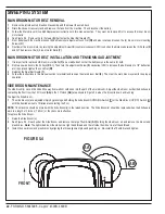
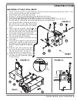
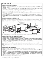
The side broom(s) move dirt and debris away from walls or curbs and into the path of the main broom. Adjust the side broom so that the bristles are
contacting the floor from the 10 O’clock
(AA)
to the 3 O’clock
(AB)
area shown in Figure 5.4 when the broom is down and running.
To adjust the Side Broom...
1
The side broom(s) are adjusted simply by pressing and holding the Side Broom DOWN/ON Switch
(P)
or the Side Broom UP/OFF Switch
(U)
until the desired amount of bristles are contacting the floor.
NOTE:
The machine should be stored with the Side Broom(s) in the raised position. The Side Broom(s) should be replaced when the bristles are
worn to a length of 3 inches (7.62 cm) or they become ineffective.
To replace the Side Broom...
1
Raise the Side Broom(s).
2
See Figure 5.5. Reach under the Side Broom and remove the large Thumb-Nut
(AC)
holding the side broom on and remove the broom and
plastic disc.
Note:
The right side broom thumb nut is a right hand thread and the left side thumb nut is a left hand thread.
3
Install the new broom and plastic disc by aligning the three alignment pins and pushing on. Re-install the Thumb-Nut and tighten.
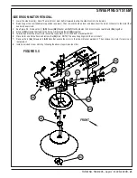
FIGURE 5.4
Summary of Contents for 56303000
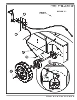
Page 17: ...FORM NO 56043096 Captor 4300B 4800B 15 FRONT WHEEL SYSTEM FIGURE 3 1...
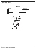
Page 20: ...18 FORM NO 56043096 Captor 4300B 4800B HYDRAULIC SYSTEM FIGURE 4 3...
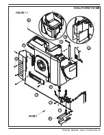
Page 33: ...FORM NO 56043096 Captor 4300B 4800B 31 SOLUTION SYSTEM FIGURE 7 1...
Page 39: ...FORM NO 56043096 Captor 4300B 4800B 37 SQUEEGEE SYSTEM FIGURE 10 1...
Page 41: ...FORM NO 56043096 Captor 4300B 4800B 39 SQUEEGEE SYSTEM FIGURE 10 2...
Page 45: ...FORM NO 56043096 Captor 4300B 4800B 43 WIRING SCHEMATIC before SN 1767238 ELECTRICAL SYSTEM...
Page 50: ......


