12
- FORM NO. 56043096 - Captor
™
4300B, 4800B
WHEEL DRIVE SYSTEM
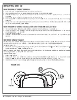
ROTARY SENSOR (DIRECTIONAL POT SETTING)
1
Open the rear electrical control panel door to access the Curtis Speed Control.
2
Disconnect the 24 pin plug from the controller.
3
With a Volt / Ohmmeter check the resistance of the rotary sensor at the plug wires WHT/BLK pin14 and VIO/BLK pin 13.
4
Divide the measured resistance in half to find the neutral setting (dead-band).
5
Move one meter lead to wire BRN/RED pin 15.
6
Position the meter on top of the tanks so it can read easily from the foot pedal.
7
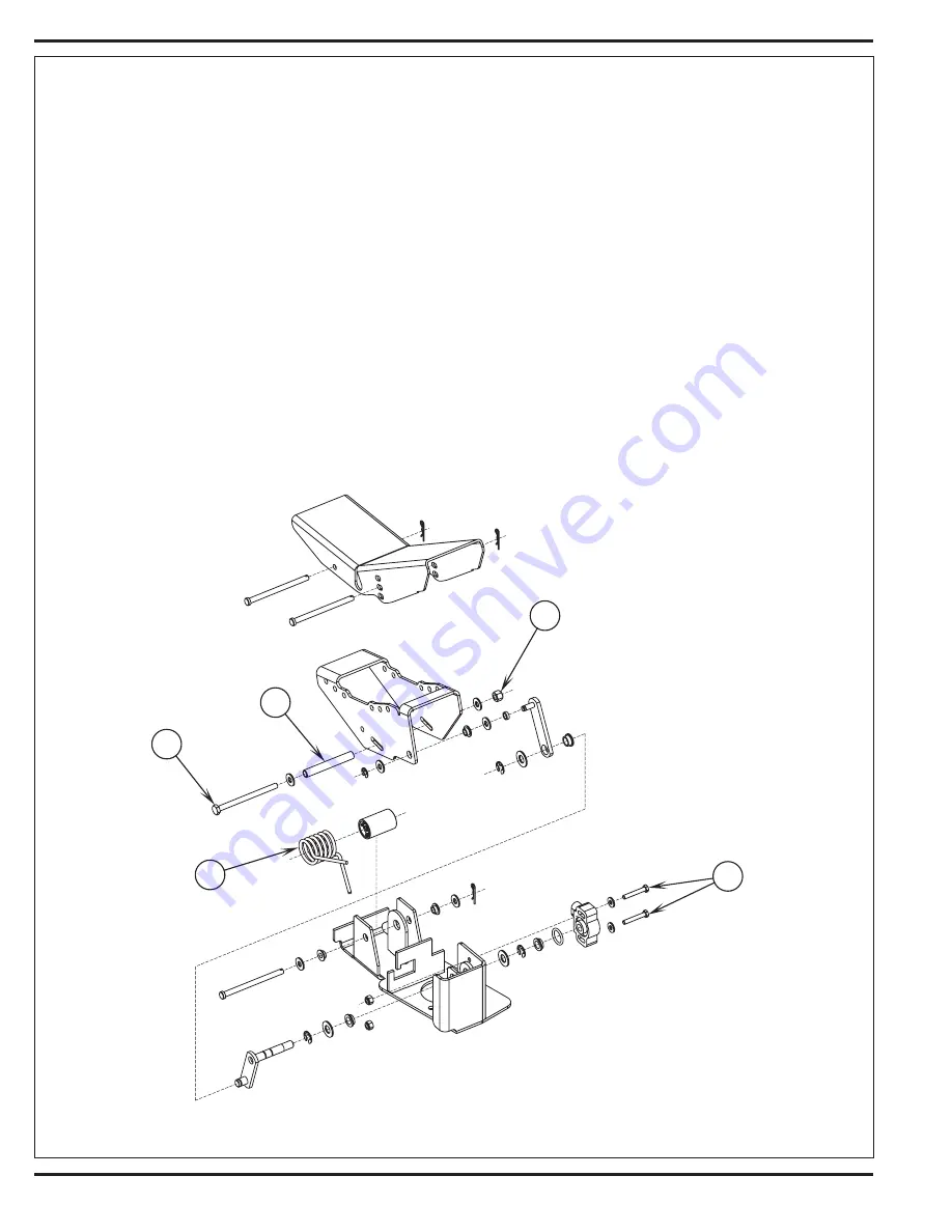
At the foot pedal loosen the 2
(Q)
Philip Screws and rotate the rotary sensor until you have reached the neutral dead-band then tighten the
Screws
(Q)
and retest the pot.
FIGURE 2.3
Summary of Contents for 56303000
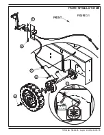
Page 17: ...FORM NO 56043096 Captor 4300B 4800B 15 FRONT WHEEL SYSTEM FIGURE 3 1...
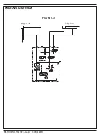
Page 20: ...18 FORM NO 56043096 Captor 4300B 4800B HYDRAULIC SYSTEM FIGURE 4 3...
Page 33: ...FORM NO 56043096 Captor 4300B 4800B 31 SOLUTION SYSTEM FIGURE 7 1...
Page 39: ...FORM NO 56043096 Captor 4300B 4800B 37 SQUEEGEE SYSTEM FIGURE 10 1...
Page 41: ...FORM NO 56043096 Captor 4300B 4800B 39 SQUEEGEE SYSTEM FIGURE 10 2...
Page 45: ...FORM NO 56043096 Captor 4300B 4800B 43 WIRING SCHEMATIC before SN 1767238 ELECTRICAL SYSTEM...
Page 50: ......


