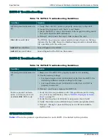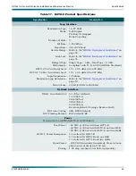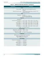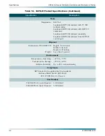
HDSL4 for General Distribution Installation and Maintenance Practice
HDSL4 Deployment Guidelines
61223HDSL4L2-5C
57
Resistance Values
Span Powering Two Repeaters with Span Powered Remote
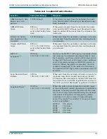
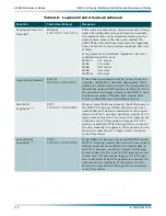
Each of the three segments associated with span powering two H4Rs and a H4TU-R must
satisfy the DC resistance budgets in addition to the recommended loop attenuation require-
ments. In general, 22 and 19 AWG segments are restricted by their loop attenuation while the
DC resistance restricts the segment reach for 26 and 24 AWG. When designing a dual H4R
loop, the first segment should have lower DC resistance than the second segment.
See
.
Single H4R spans do not require any restriction due to DC resistance.
NOTE
A circuit that otherwise meets attenuation and other requirements
for cable reach will encounter span powering problems if resistance
values are excessive.
The segment resistance (
Ω
segment
) is determined using this equation:
Ω
segment
= L
26
*
Ω
26
+ L
24
*
Ω
24
+ L
22
*
Ω
22
+ L
19
*
Ω
19
where L
#
is the length of # AWG cable (in kilofeet, excluding bridged taps)
and where
Ω
26
is the DC resistance of #AWG cable.
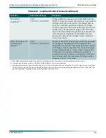
Once the resistance of each segment is confirmed, refer to
to decide if the H4TU-C
is capable of span powering two H4Rs and one H4TU-R. Alternatively, the DSL Assistant
program will automatically calculate this and report any violations.
Table 14. Single Pair DC Resistance Value
Resistance (ohms/kilofoot)
AWG
70°F
90°F
120°F
140°F
19
16.465
17.183
18.261
18.979
22
33.006
34.446
36.606
38.046
24
52.498
54.789
58.225
60.516
26
83.475
87.117
92.581
96.223
Note: Interpolated between 70
°
F and 120
°
F data. Extrapolated from 70
°
F and 120
°
F data.


