113546 - 2
www.adclaundry.com
7
NOTE:
The manufacturer reserves the right to make changes in specifications at any time without notice or obligation.
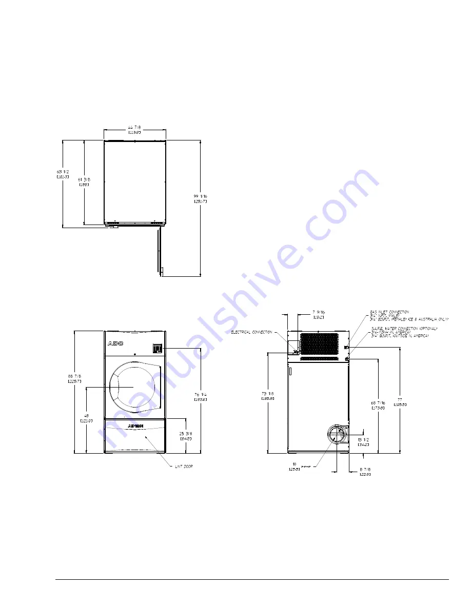
Specifications _____________________________________________________________________
Page 1: ...isin Suivez les instructions du fournisseur Si vous ne pouvez rejoindre le fournisseur de gaz appelez le service des incendies L installation et l entretien doivent tre assur s par un installateur ou...
Page 2: ...ur order is processed accurately and promptly These instructions are only valid if the following country code is on the appliance If this code is not present on the appliance it is necessary to refer...
Page 3: ...he following installation instructions apply Installations and repairs must be performed by a qualified or licensed contractor plumber or gasfitter qualified or licensed by the State of Massachusetts...
Page 4: ...terials Drying in a heated tumbler may damage plastics or rubber and also may be a fire hazard The possible presence of residual quantities of aggressive or decomposed chemicals in the load may produc...
Page 5: ..._ ______________________________________________________________ ______________________________________________________________ ______________________________________________________________ _________...
Page 6: ...IRBORNE SOUND LEVEL 69 dB A DRYERS PER 20 40 CONTAINER 4 9 DRYERS PER 48 53 TRUCK 10 12 VOLTAGE AVAILABLE 208 480V 1 3 2 3 4w 50 60 Hz APPROXIMATE NET WEIGHT 1 440 lb 653 17 kg APPROXIMATE SHIPPING WE...
Page 7: ...claundry com 7 NOTE The manufacturer reserves the right to make changes in specifications at any time without notice or obligation Specifications ______________________________________________________...
Page 8: ...tible construction as noted in this manual refer to Dryer Enclosure Requirements section Provisions must be made for adequate clearances for servicing and for operation as noted in this manual refer t...
Page 9: ...onsole Module 1 Remove the outer top top back guard bottom back guard and rear electrical box cover refer to the Component Identification drawing 2 Remove 8 bolts washers and lock washers L figure 1 t...
Page 10: ...o its mating plug This plug is similar to the one in the lower right corner that was disconnected earlier 9 Reinstall the retaining screws top and bottom 10 Reinstall the bottom hinge block This was t...
Page 11: ...e exhaust ductwork system Exhaust back pressure measured by a manometer magnehelic in the exhaust duct must be no less than 0 and must not exceed 0 7 in WC 1 7 mb Fresh Air Supply Requirements _______...
Page 12: ...e nearest obstruction refer to the diagram Exhaust Transition Piece This dryer is equipped with a 12 inch to 10 inch exhaust transition piece installed for use with 10 inch ducting If the exhaust duct...
Page 13: ...proper venting information Multiple Dryer Common Venting If it is not feasible to provide separate exhaust ducts for each dryer ducts from individual dryers may be channeled into a common main duct T...
Page 14: ...14 American Dryer Corp 113546 2 MULTIPLE DRYER VENTING HORIZONTAL AT COMMON DUCT MULTIPLE DRYER VENTING VERTICAL AT COMMON DUCT...
Page 15: ...wire size 4 24 14 Not available until September 2014 Grounding A ground earth connection must be provided and installed in accordance with local state and national regulations or codes of the country...
Page 16: ...be grounded A ground lug has been provided for this purpose Input connection wiring must be sized properly to handle the dryer s current draw This information is printed on the dryer s rating plate I...
Page 17: ...re the input wiring enters 3 Phase 3 Wiring Connections Hookup The electrical connections on all 3 phase 3 gas and steam dryers are made into the rear service box located at the upper left area of the...
Page 18: ...atings shown on the rating plate are for elevations up to 2 000 feet 610 meters unless elevation requirements of over 2 000 feet 610 meters were specified at the time the dryer order was placed with t...
Page 19: ...Input Gas Consumption Orifice Injector Data For CE European Models Only GAS SPECIFICATIONS FOR NON CE APPROVED DRYERS Gas Type Nominal Heating Value Supply Pressure Gross Heat Input Orifice Size Orif...
Page 20: ...ccessible for a pressure gauge connection must be installed in the main gas supply line immediately upstream of the dryers IMPORTANT Pipe joint compounds that resist the action of natural L P and buta...
Page 21: ...tructions included in kit envelope 92 1022 supplied 9 To convert the gas valve for use with regulated L P gas refer to the instructions included in kit envelope 92 0659 supplied 10 Reverse procedure f...
Page 22: ...ly a glass or transparent plastic tube with a scale graduated in inches or millibars When it is filled with water and pressure is applied the water in the tube rises showing the exact gas pressure Gas...
Page 23: ...ly in place Be sure the lint door drawer is securely in place Rotate the tumbler drum by hand to be sure it moves freely Check bolts nuts screws terminals and fittings for tightness and security Check...
Page 24: ...mation ___________ Service Service must be performed by a qualified trained technician If service is required contact the reseller from whom the equipment was purchased If the reseller cannot be conta...
Page 25: ...t be accepted IMPORTANT No replacements credits or refunds will be issued if the claim cannot be processed due to insufficient information The party filing the claim will be notified in writing either...
Page 26: ...exhaust and ventilation gases reducing dryer performance Cleaning of the dryer s internal exhaust may require removing the lint screen See the instructions above for removing the lint screen Check an...
Page 27: ...____ ______________________________________________________________ ______________________________________________________________ ______________________________________________________________ ______...
Page 28: ...IL SWITCH CLOSED FAULT Sail switch is closed should be open at the start of a cycle O O O SAIL SWITCH OPEN FAULT Sail switch remained open after the cycle started Should have closed BURNER HIGH LIMIT...
Page 29: ...closed before starting SAIL SWITCH OPEN Sail switch failed to close after starting BURNER HI LIMIT Oven thermostat switch has opened EXHAUST HI LIMIT Tumbler thermostat switch has opened BURNER CONTRO...
Page 30: ...ADC Part No 113546 2 08 13 14...