background image

Installation and Commissioning Guide

Package Commercial Unit


51

Installation and Commissioning Guide - Package Commercial Unit

Doc. Part No. 0525-055   Ver. 9  220308

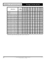
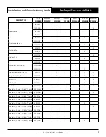
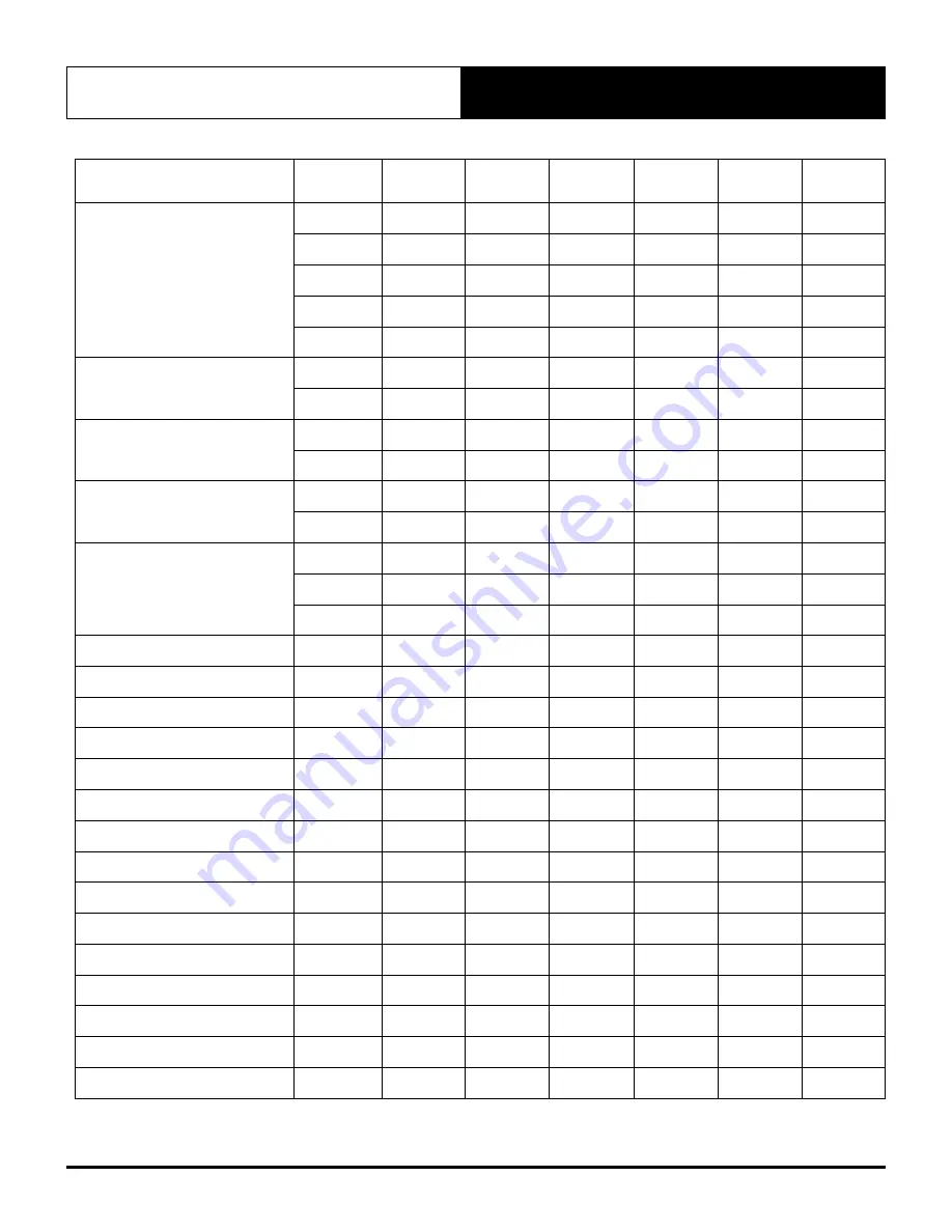
DESCRIPTION

PART

NUMBER

PCG290L

PCG290R

PCG300L

PCG300R

PCG330L

PCG330R

PCG340L

PCG340R

PCG400L

PCG400R

PKA300T-L  

PKA300T-R

Compressor

1560-437

1

-

-

-

-

-

1560-440

-

2

-

-

-

2

1560-438

-

-

1

-

-

-

1560-463

-

-

-

2

-

-

1560-459

-

-

-

-

2

-

Crankcase Heater

2025-006

1

-

1

-

-

-

2025-005

 -

2

-

2

2

2

Outdoor Fan

2505-106

2

2

2

2

-

2

2505-134

-

-

-

-

2

-

Indoor Fan

2520-029

2

2

2

2

-

2

2520-326

-

-

-

-

2

-

Outdoor Control Board

2020-097

1

-

1

-

-

-

2020-045

-

1

-

1

-

1

2020-100

-

-

-

-

1

-

Indoor Control Board - CPI

2020-101

1

1

1

1

1

1

Stage 2 Control Board

2020-009

-

1

-

1

1

1

ECM Filter

4080-013

2

2

2

2

2

2

HP Switch

2060-019

1

2

1

2

2

2

LP Switch

2060-020

1

2

1

2

2

2

Metering Device - (0.0625”) Piston

4540-062

2

-

2

-

-

-

Metering Device - (0.0670”) Piston

4540-067

-

2

-

-

-

2

Metering Device - (0.0689”) Piston 4540-068

-

-

-

2

-

-

Metering Device - (0.0748”) Piston

4540-074

2

-

-

-

-

-

Metering Device - (0.0760”) Piston

4540-076

-

-

-

-

2

-

Metering Device - (0.0781”) Piston

4540-078

-

-

-

-

-

2

Metering Device - (0.0846”) Piston 4540-084

-

2

-

-

-

-

Metering Device - (0.0860”) Piston 4540-086

-

-

-

2

-

-

Metering Device - (0.0880”) Piston 4540-088

-

-

2

-

-

-

Metering Device - (0.0945”) Piston

4540-094

-

-

-

-

2

-

Summary of Contents for PCA300U Series

Page 1: ...PCG233U PCG260U PCG290U PCA300U PCA330U PCG330U PCA340U PCG340U PCG400U PCG153V PCG173V PCG203V PCG233V PCG260V PCG290V PCA300V PCA330V PCG330V PCA340V PCG340V PCG400V PCG290L PCG300L PCG330L PCG340L PCG400L PCG290R PCG300R PCG330R PCG340R PCG400R PKA300T LFFT EA PKA300T RFFT EA Above images shown are for illustration purposes only LH Air Handing Option RH Air Handing Option Under Over Indoor Coil...

Page 2: ...14 09 Banking of Units 15 10 Unit Lifting Procedure 17 11 Condensate and Safety Tray Drainage Instructions 19 12 Electrical Installation 20 13 Package Unit Electrical Connection 21 14 Maximum Cable Length 22 15 Standard Indoor Fan Commissioning 23 16 EC Indoor Fan Commissioning 25 16 01 PCG153U V to PCG233U V 25 16 02 PCG260U V to PCG400U V L R add PKA300T L R 26 17 Indoor Fan Table And Fan Curve ...

Page 3: ...is manual to indicate immediate or potential hazards Pay full attention and comply to the safety information and instructions Failure to follow safety instructions increases the risks of personal injury death and or property damage Damages to the product as a result of such failure may void warranty ActronAir has endeavored to provide sufficient safety warnings and recommendations however current ...

Page 4: ...ditions The galvanized steel cabinet with powder coated epoxy enamel finish resists the toughest conditions The louvered outdoor coil guard protects the condenser coil from any potential damage brought by hail stones and other solid objects that may be projected to the unit Hydrophilic blue coil fins provide protection to your heat exchangers and enhanced heat transfer with increased performance e...

Page 5: ...d to ensure that they do not play with the appliance Installer must incorporate a means of electrical disconnection isolator in the sub mains fixed wiring in accordance with the latest edition of the AS NZS 3000 also known as Australian Wiring Rules Secure the power cords and control cables that goes in out the unit Use the cable ties provided in the control box This unit is designed for use with ...

Page 6: ... rise above 500 microns indicates a leak from the system and a leak test is required to locate and repair any leak CAUTION A leak test is always required on any repaired section of the refrigeration system Charge refrigerant into the system only after the equipment does not leak or contain moisture Ensure that R 410A is only charged in liquid form Take into consideration the correct amount of refr...

Page 7: ...PROJECTION 0525 0XX Install Guide Commercial Pack V1 Page 5 4 D E F C B A 3 2 1 5 C D 4 6 7 8 A B 0525 0XX Install Guide Commercial Pack V1 A3 SHEET 1 OF 1 N T S DRAWING NO MATERIAL DESCRIPTION DATE DRAWN BY APPROVED BY SCALE DRAWN DATE DESCRIPTION FINISH REV PCR F E REV BY 7 3 1 HOLE DIAMETER A B N 34 002 767 240 PH 61 2 8814 4000 Bella Vista NSW 2153 Norwest Business Park 5 Irvine Place written ...

Page 8: ... INDOOR FAN INDOOR FAN PCG203U 50 POWER SUPPLY ENTRY Ø 32mm Ø 25 mm COMP SIDE CONDENSATE POINTS CONDENSATE DRAIN Ø 25mm ID NOTES 1 Do not scale drawing All dimensions are in mm unless specified Refer to corresponding unit dimensional drawing for mounting hole details 2 Ensure that Service Access Areas and Spaces for Airflow Clearances are met This is based on the condition that the spaces around t...

Page 9: ... W RD 50 SUPPLY AIR OUTDOOR AIR INLET OUTDOOR AIR INLET RETURN AIR A MTG C C DIST OUTDOOR AIR OUTLET POWER SUPPLY ENTRY Ø 40mm Ø 25mm CONDENSATE POINTS COMP SIDE CONDENSATE DRAIN POINTS NOTES 1 Do not scale drawing All dimensions are in mm unless specified Refer to corresponding unit dimensional drawing for mounting hole details 2 Ensure that Service Access Areas and Spaces for Airflow Clearances ...

Page 10: ...IR INLET OUTDOOR AIR INLET INDOOR COIL FAN INDOOR FAN INDOOR FAN L W SD W RD CONDENSATE POINTS W CONDENSATE DRAIN Ø 25mm ID 50 NOTES 1 Do not scale drawing All dimensions are in mm unless specified Refer to corresponding unit dimensional drawing for mounting hole details 2 Ensure that Service Access Areas and Spaces for Airflow Clearances are met This is based on the condition that the spaces arou...

Page 11: ...5 x 1595 2 x Ø 25 4 1 ID BSP FEMALE THREAD D NOTES 1 Do not scale drawing All dimensions are in mm unless specified Refer to corresponding unit dimensional drawing for mounting hole details 2 Ensure that Service Access Areas and Spaces for Airflow Clearances are met This is based on the condition that the spaces around the units are free from any obstructions and a walkway passage of 1000mm betwee...

Page 12: ...ing for mounting hole details 2 Ensure that Service Access Areas and Spaces for Airflow Clearances are met This is based on the condition that the spaces around the units are free from any obstructions and a walkway passage of 1000mm between the units or between the unit and the outside perimeter is available 3 Minimum service access areas and spaces for airflow clearances are responsibilities of ...

Page 13: ... for mounting hole details 2 Ensure that Service Access Areas and Spaces for Airflow Clearances are met This is based on the condition that the spaces around the units are free from any obstructions and a walkway passage of 1000mm between the units or between the unit and the outside perimeter is available 3 Minimum service access areas and spaces for airflow clearances are responsibilities of the...

Page 14: ...44 9 142 9 300 800 750 1 PCG330U V 470 41 5 44 9 150 9 44 9 44 9 142 9 300 800 750 1 PCG330L 480 46 6 46 6 134 1 54 3 46 6 151 8 300 800 750 1 PCG330R 480 134 1 46 6 46 6 54 3 46 6 151 8 300 800 750 1 PCA340U V 500 62 0 53 4 129 3 52 4 53 4 149 5 300 800 750 2 PCG340U V 500 62 0 53 4 129 3 52 4 53 4 149 5 300 800 750 2 PCG340L 500 62 0 53 4 129 3 52 4 53 4 149 5 300 800 750 2 PCG340R 500 129 3 53 ...

Page 15: ... For Airflow In A Well Ventilated Area Models A Compressor and Electrical Clearance Outdoor Coil Airflow Clearance Height Clearance B C D PCG153U V PCG173U V PCG203U V Duct Work 600 300 300 1500 PCG233U V PCG260U V Duct Work 800 600 300 1500 PCG290U V PCA300U V PCA330U V PCG330U V PCA340U V PCG340U V PCG400U V PCG290L R PCG300L R PCG330L R PCG340L R PCG400L R Duct Work 800 750 300 1500 PKA300T L P...

Page 16: ...IL FAN Airflow Allowance COMP Service Clearances Compressor and Electricals Fan B A D B C Airflow Allowance C Airflow Allowance D D Side By Side Configuration COMP COMP COMP Unit 2 or 3 Service Clearance and Airflow Allowance OUTDOOR COIL Duct Work Duct Work UNIT 3 OUTDOOR COIL INDOOR COIL FAN Airflow Allowance COMP Service Clearances Compressor and Electricals Fan B A C Airflow Allowance Unit 1 S...

Page 17: ...mended for high rise lifting DETAIL A PACKAGE UNIT PALLET Slip nylon slings through the pallet A Fig 1 Connect the loop ends of slings into shackle RUBBER PADS Provide rubber pads to prevent damage to the unit NOTES Undo the screws holding down the unit unto the pallet before removing the pallet Unit show above is for illustration purposes only Refer to Unit Dimensions and Clearances section for u...

Page 18: ...rigging equipment accessories and plant are sufficiently and safely capable to lift the unit in order to prevent potential damage to property severe personal injury or death Check unit weight and weight distribution points on unit drawing dimensions section NOTES Lifting procedure and unit model shown are suggestions and for illustration purposes only It is highly recommended that installer observ...

Page 19: ...p of the Vent must be 50mm higher than the top of the Evaporator Condensate Tray 250mm or high enough to maintain positive Air Seal Condensate Drain Connection Trap Clear Plastic Inspection Tube 125mm NOTES PCG model shown for illustration purposes only Suggested condensate drainage connection and details are also applicable to PCA models Ensure that Condenser and Evaporator condensate drains are ...

Page 20: ...onditioning system is located on the inside panel of the control access door Always refer all wiring installation servicing and troubleshooting of this equipment to this diagram to ensure correct electrical connections are satisfied Supply Power Requirements and Procedures It is the installer s responsibility to provide power supply wiring to the sub mains isolator Wiring should conform to the cur...

Page 21: ...plied by Installer 2 MAIN SUPPLY FROM DISTRIBUTION BOARD SUB MAIN TO UNIT SUB MAINS ISOLATOR Field Supplied by Installer 1 PACKAGE UNIT CIRCUIT BREAKER SIZE AND CABLE SIZE REQUIREMENT Model Circuit Breaker Size Cable Size mm2 Amps Main PCG153U V PCG173U V PCG203U V 20 0 2 5 PCG233U V 25 0 4 0 PCG260U V PCG290U V PCA300U V PCA330U V PCG330U V PCA340U V PCG340U V PKA300T L R PCG290L R PCG300L R 32 0...

Page 22: ...COOL RUN STAGE ROOM MON TUE WED THU FRI SAT SUN TIMER FILTER AH AM PM SETBACK EVENT 1 2 oC TIME CLOCK ON OFF PACKAGE UNIT 1 2 CORE 14 0 20 0 44mm Shielded Data Cable NOTES Diagram shown above is a general representation only Refer to individual unit wiring diagram for complete wiring connection details Long runs beside Mains cables or TV antenna cables should be avoided where possible Item Descrip...

Page 23: ...D DIP SWITCH SETTINGS STEP DE ICE CANCEL TIMERS SET TO 7 DAY INDOOR FAN CONNECTIONS TERMINALS CONNECTION A CONNECTION B NEUTRAL AC INDOOR FAN IFRC H L M IF 1 1 EARTH HIGH MED LOW NEUTRAL The DIP switch is set on The DIP switch is set on DUAL SPEED INDOOR FAN DUAL SPEED INDOOR FAN INDOOR UNIT Step 2 An option to choose a 1 Speed Setting is available for the End User Customer This can be done by set...

Page 24: ...e shown The factory default settings are as shown in the table below VOLT FREE CONTACTS BY OTHERS OCB CONDENSER CPU BOARD NEUT COMP LP LP HP HP REV NEUT NEUT LOW HIGH ACT NEUT EARTH NEUT ACT HIGH LOW NEUT COMP FAN HEAT 15V DATA COM SCREEN 1 DEF 2 FAN 3 COM 240V MAINS OUT 240V INDOOR FAN ALL C SERIES CONTROLS SET TO 7 DAY COOL ONLY ON STAGE 2 ON BOOST HEAT ON WALL CONTROL CONT FAN SINGLE SPEED INDO...

Page 25: ...1 P1 V2 1 U4 U3 R11 R12 R13 R14 R15 C5 D3 R3 R4 C7 R2 R1 RV1 TRA 0100 R D1 D2 P5 INPUT R10 C8 P6 GND 0 10V PWM1 OUT DAMAGE DUE TO INCORRECT WIRING VOIDS WARRANTY CPI3 2 S N XXXXXXXX IF ON OFF IF PWR 240VAC IN ActronAir LED FAN PWM DISPLAY CPI3 2 COMMERCIAL PWM INDOOR BOARD JUMPER PIN SET AS PER TABLE BELOW PWM ADJUSTMENT POTENTIOMETER Step 3 Using the fan table provided below select the correspond...

Page 26: ...USED B PCG153U V C 64 84 98 PCG173U V D 66 88 99 PCG203U V E 52 68 88 PCG233U V F 46 67 99 16 02 PCG260U V to PCG400U V L R add PKA300T L R Fan Adjustment Procedure Step 1 Locate CPI Fan Controller Package Systems Outdoor Section Electrical Pane Step 2 Turn ON the unit through the installed wall controller or thermostat CPI 3 23787 3 C3 DISP2 DISP1 MODEL A B C D E F ADJUST V2 C2 P3 C1 P1 P2 V1 0 U...

Page 27: ...ckwise to increase the PWM and counter clockwise to lower the PWM PWM FAN SPEED ADJUSTMENT PWM _ NOTES LED will show PWM without Example 71 PWM 71 in LED LED adjustments are in 1 digit increment JUMPER PIN POSITION AND CPI PWM RANGE Table below shows factory default jumper position to corresponding air conditioning models to limit fan operating range Refer to specific fan performance data and fan ...

Page 28: ...ncrements CPI 3 23787 3 C3 DISP2 DISP1 MODEL A B C D E F ADJUST V2 C2 P3 C1 P1 V2 1 U4 U3 R11 R12 R13 R14 R15 C5 D3 R3 R4 C7 R2 R1 RV1 TRA 0100 R D1 D2 P5 INPUT R10 C8 P6 GND 0 10V PWM1 OUT DAMAGE DUE TO INCORRECT WIRING VOIDS WARRANTY CPI3 2 S N XXXXXXXX IF ON OFF IF PWR 240VAC IN ActronAir LED FAN PWM DISPLAY JUMPER PIN SET AS PER TABLE BELOW PWM ADJUSTMENT POTENTIOMETER NOTES Performance Fan Cu...

Page 29: ...an Power Watts PWM Pulse Width Modulation Setting PWM Adjustable through CPI3 2 Board located in electrical panel Factory PWM Setting 88 PWM for 100 Pa Data in the box indicates Factory Default Setting JUMPER PIN POSITION INDOOR FAN A NOT USED B NOT USED C PCG153U V D PCG173U V E PCG203U V F PCG233U V CPI3 2 RESIDENTIALPWMINTERFACEBOARD NOTES LED will show PWM without Example 88 PWM 88 in LED LED ...

Page 30: ...ication 2 5 m s face velocity point will occur at 1200 l s NOTES W Indoor Fan Power Watts PWM Pulse Width Modulation Setting PWM Adjustable through CPI3 2 Board located in electrical panel Factory PWM Setting 68 PWM for 100 Pa Data in the box indicates Factory Default Setting JUMPER PIN POSITION INDOOR FAN A NOT USED B NOT USED C PCG153U V D PCG173U V E PCG203U V F PCG233U V CPI3 2 RESIDENTIALPWMI...

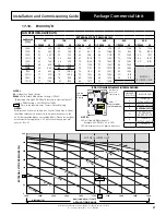
Page 31: ... 1300 73 687 77 781 82 885 98 1012 1325 75 707 80 829 85 939 1350 78 757 82 851 89 972 1375 80 780 85 896 94 1025 1380 81 798 86 912 95 1035 MOTOR BLOWER LIMIT NOTES Performance Fan Curve shown is at Dry Coil Condition Airflow should be reduce with respect to the moisture content in the air All data provided does not include filters Please review filter manufacturer for application 2 5 m s face ve...

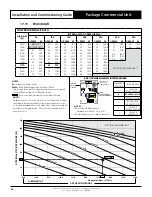
Page 32: ...PWM Adjustable through CPI3 2 Board located in electrical panel Factory PWM Setting 78 PWM for 100 Pa Data in the box indicates Factory Default Setting JUMPER PIN POSITION INDOOR FAN A SCG400E PCG400U V L R B PCG340U V L R C PCG330U V L R D PCG300L R PKA300L R E SCG290E PCG290U V L R F SRG260E PCG260U V CPI3 1 COMMERCIALPWMINTERFACEBOARD NOTES LED will show PWM without Example 78 PWM 78 in LED LED...

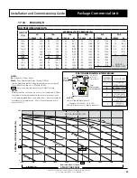
Page 33: ...Fan Power Watts PWM Pulse Width Modulation Setting PWM Adjustable through CPI3 2 Board located in electrical panel Factory PWM Setting 61 PWM for 100 Pa Data in the box indicates Factory Default Setting JUMPER PIN POSITION INDOOR FAN A SCG400E PCG400U V L R B PCG340U V L R C PCG330U V L R D PCG300L R PKA300L R E SCG290E PCG290U V L R F SRG260E PCG260U V CPI3 1 COMMERCIALPWMINTERFACEBOARD NOTES LED...

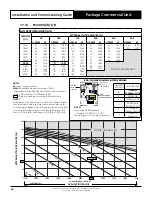
Page 34: ...e Width Modulation Setting PWM Adjustable through CPI3 2 Board located in electrical panel Factory PWM Setting 61 PWM for 100 Pa Data in the box indicates Factory Default Setting JUMPER PIN POSITION INDOOR FAN A SCG400E PCG400U V L R B PCG340U V L R C PCG330U V L R D PCG300L R PKA300T L R E SCG290E PCG290U V L R F SRG260E PCG260U V CPI3 1 COMMERCIALPWMINTERFACEBOARD NOTES LED will show PWM without...

Page 35: ...se Width Modulation Setting PWM Adjustable through CPI3 2 Board located in electrical panel Factory PWM Setting 61 PWM for 100 Pa Data in the box indicates Factory Default Setting JUMPER PIN POSITION INDOOR FAN A SCG400E PCG400U V L R B PCG340U V L R C PCG330U V L R D PCG300L R PKA300T L R E SCG290E PCG290U V L R F SRG260E PCG260U V CPI3 1 COMMERCIALPWMINTERFACEBOARD NOTES LED will show PWM withou...

Page 36: ... at 2156 l s NOTES W Indoor Fan Power Watts PWM Pulse Width Modulation Setting PWM Adjustable through CPI3 2 Board located in electrical panel Factory PWM Setting 69 PWM for 100 Pa Data in the box indicates Factory Default Setting JUMPER PIN POSITION INDOOR FAN A SCG400E PCG400U V L R B PCG340U V L R C PCG330U V L R D PCG300L R PKA300T L R E SCG290E PCG290U V L R F SRG260E PCG260U V CPI3 1 COMMERC...

Page 37: ...nt will occur at 2156 l s NOTES W Indoor Fan Power Watts PWM Pulse Width Modulation Setting PWM Adjustable through CPI3 2 Board located in electrical panel Factory PWM Setting 69 PWM for 100 Pa Data in the box indicates Factory Default Setting JUMPER PIN POSITION INDOOR FAN A SCG400E PCG400U V L R B PCG340U V L R C PCG330U V L R D PCG300L R PKA300T L R E SCG290E PCG290U V L R F SRG260E PCG260U V C...

Page 38: ... at 2156 l s NOTES W Indoor Fan Power Watts PWM Pulse Width Modulation Setting PWM Adjustable through CPI3 2 Board located in electrical panel Factory PWM Setting 69 PWM for 100 Pa Data in the box indicates Factory Default Setting JUMPER PIN POSITION INDOOR FAN A SCG400E PCG400U V L R B PCG340U V L R C PCG330U V L R D PCG300L R PKA300T L R E SCG290E PCG290U V L R F SRG260E PCG260U V CPI3 1 COMMERC...

Page 39: ...nt will occur at 2156 l s NOTES W Indoor Fan Power Watts PWM Pulse Width Modulation Setting PWM Adjustable through CPI3 2 Board located in electrical panel Factory PWM Setting 69 PWM for 100 Pa Data in the box indicates Factory Default Setting JUMPER PIN POSITION INDOOR FAN A SCG400E PCG400U V L R B PCG340U V L R C PCG330U V L R D PCG300L R PKA300T L R E SCG290E PCG290U V L R F SRG260E PCG260U V C...

Page 40: ...or PCG400L R NOTES W Indoor Fan Power Watts PWM Pulse Width Modulation Setting PWM Adjustable through CPI3 2 Board located in electrical panel Factory PWM Setting 71 PWM for 100 Pa Data in the box indicates Factory Default Setting JUMPER PIN POSITION INDOOR FAN A SCG400E PCG400U V L R B PCG340L R C PCG330U V L R D PCG300L R PKA300T L R E SCG290E PCG290U V L R F SRG260E PCG260U V CPI3 1 COMMERCIALP...

Page 41: ...nt R 410A refrigerant must always be charged in liquid state Only during the compressor running condition the system can be charged through the suction service port on the compressor suction line Changes in refrigerant charge must be noted to a label that is fixed to the unit for future reference CAUTION The system of this unit operates with POE oil that rapidly absorbs moisture The maximum time a...

Page 42: ...on line temperature for all of the refrigeration circuits STAGE 1 STAGE 2 If Applicable Discharge Pressure kPa Discharge Pressure kPa Liquid Line Temperature LLT C Liquid Line Temperature LLT C Suction Pressure kPa Suction Pressure kPa Suction Line Temperature SLT C Suction Line Temperature SLT C NOTE Accurate pressure and temperature measuring tools should be used to achieve satisfactory results ...

Page 43: ...um it means that liquid refrigerant may be returning to compressor It is necessary to remove refrigerant If superheat is higher than maximum it means that refrigeration capability of evaporator is not fully maximised It is necessary to add refrigerant charge Allow the systems to stabilise 15 30 mins and repeat the step 1 3 until superheat falls within the range specified in the table below Models ...

Page 44: ...5 2621 8 50 10 7 18 332 6 14 1119 2 46 2686 2 49 16 3 17 348 7 15 1154 6 47 2751 8 48 22 2 16 365 2 16 1190 7 48 2818 5 47 28 2 15 382 3 17 1227 5 49 2886 4 46 34 0 14 399 7 18 1265 2 50 2955 5 45 40 9 13 417 7 19 1303 6 51 3025 7 44 47 8 12 436 2 20 1342 9 52 3097 2 43 54 8 11 455 1 21 1382 9 53 3169 9 42 62 1 10 474 6 22 1423 9 54 3243 7 41 69 6 9 494 6 23 1465 7 55 3318 9 40 77 4 8 515 1 24 150...

Page 45: ...e maintenance procedures can result in serious injury and or death Annual Maintenance Checklists Perform general maintenance inspections Perform scheduled start up checks Leak test refrigerant circuits Inspect contacts of all contactors and relays Replace all worn contacts as required Inspect clean and tighten all electrical connections Check fans for balanced operation Make sure that there are no...

Page 46: ... the coils if they are still dirty repeat the cleaning procedure Clean and wipe dry the outer and inner sides of the unit the refrigerating parts and other components Ensure that the condensate drain lines are not blocked Reinstall all unit panels covers and guards Restore electrical power to the unit CAUTION Be Careful Not to Spray Water into the Electrical Components 20 Maintenance Frequency Che...

Page 47: ... dust as necessary to negate possibility of fan running out of balance Motor Ω Visual check on wiring Insulation resistance check to be carried out annually Measure insulation resistance to earth with insulation tester Insulation resistance should be more than 1MΩ Heat Exchanger Check for clogging by dust Check for leaks damage Clean air inlet side as necessary Straighten any bent fins using fins ...

Page 48: ...ck for clogging by dust Check for leaks damage Clean air inlet side as necessary Straighten any bent fins using fins comb Condensate Drain Line if available Check for obstructions and free flow of water Clean to eliminate obstructions sludge and check condition of drain line Pour water to ensure free flow Compressor Ω Check for high low pressure Measure insulation resistance Check compressor for a...

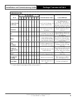
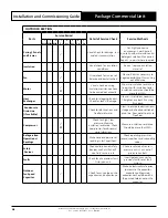
Page 49: ...U V PCG400U V Compressor 1560 440 1 2 1560 463 1 2 2 1560 462 1 1560 471 1 1560 436 1 1560 437 1 1560 438 1 1 1560 459 2 Crankcase Heater 2025 006 1 1 1 1 2025 005 2 2 2 2 Outdoor Fan 2505 109 2 2 2 2505 130 2 2 2505 106 2 2 2 2 2 2 2505 134 2 Indoor Fan 2520 338 1 1 2520 340 1 2520 313 1 1 2520 329 1 1 1 2520 324 1 1 1 2520 327 1 Outdoor Control Board 2020 151 1 1 1 1 2020 097 1 1 1 2020 045 1 1 ...

Page 50: ... 0 0591 Piston 4540 059 1 Metering Device 0 0610 Piston 4540 061 1 Metering Device 0 065 Piston 4540 065 2 Metering Device 0 0670 Piston 4540 067 2 Metering Device 0 0689 Piston 4540 068 1 1 2 2 2 2 Metering Device 0 0748 Piston 4540 074 1 2 Metering Device 0 0760 Piston 4540 076 1 2 Metering Device 0 0846 Piston 4540 084 1 2 Metering Device 0 0880 Piston 4540 088 1 2 2 Metering Device 0 0906 Pist...

Page 51: ...2 2 2520 326 2 Outdoor Control Board 2020 097 1 1 2020 045 1 1 1 2020 100 1 Indoor Control Board CPI 2020 101 1 1 1 1 1 1 Stage 2 Control Board 2020 009 1 1 1 1 ECM Filter 4080 013 2 2 2 2 2 2 HP Switch 2060 019 1 2 1 2 2 2 LP Switch 2060 020 1 2 1 2 2 2 Metering Device 0 0625 Piston 4540 062 2 2 Metering Device 0 0670 Piston 4540 067 2 2 Metering Device 0 0689 Piston 4540 068 2 Metering Device 0 ...

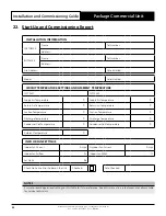
Page 52: ...upply Air Temperature C Supply Air Temperature C Return Air Temperature C Return Air Temperature C Suction Temperature C Suction Temperature C Discharge Temperature C Discharge Temperature C Condenser Coil Temperature C Condenser Coil Temperature C Ambient Temperature C INDOOR FAN SETTINGS Indoor Fan Current Amps Outdoor Fan Current Amps Indoor Fan Airflow l s Indoor Fan PWM Set Static Pa Check No...

Page 53: ...THIS PAGE WAS INTENTIONALLY LEFT BLANK ...

Page 54: ...THIS PAGE WAS INTENTIONALLY LEFT BLANK ...

Page 55: ...THIS PAGE WAS INTENTIONALLY LEFT BLANK ...

Page 56: ...efrigerant Trading Authorisation No AU06394 Copyright 2022 Actron Engineering Pty Limited ABN 34 002767240 Registered Trade Marks of Actron Engineering Pty Limited ActronAir is constantly seeking ways to improve the design of its products therefore specifications are subject to change without notice ...

Reviews: