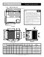


Installation and Commissioning Guide
Package Commercial Unit
27
Installation and Commissioning Guide - Package Commercial Unit
Doc. Part No. 0525-055 Ver. 9 220308
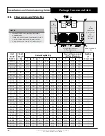
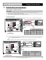
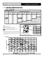
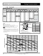
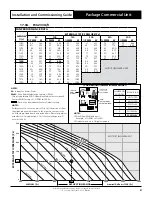
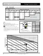
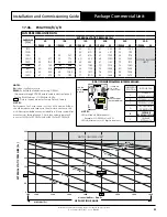
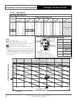
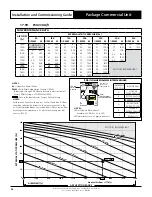
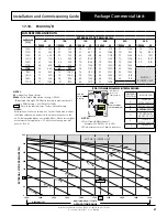
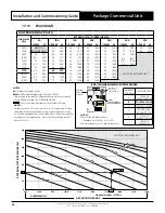
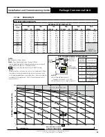
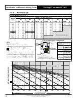
Step 3. Using the fan table provided below, select the corresponding fan %PWM by plotting the external static pressure
requirement (duct static pressure) and nominal airflow requirement of the unit. (Data may need to be calculated
to get the desired value).
Step 4. Using slotted screwdriver adjust CPI board 0-99% PWM output by rotating the potentiometer to obtain the
desired %PWM. Clockwise to increase the %PWM and counter-clockwise to lower the %PWM.
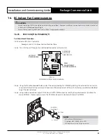
+
%PWM
FAN SPEED
ADJUSTMENT
%PWM
_
NOTES
• LED will show PWM without %.
Example: 71% PWM = 71 in LED.
• LED adjustments are in 1 digit increment.
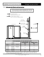
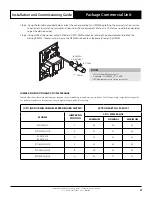
JUMPER PIN POSITION AND CPI% PWM RANGE
Table below shows factory default jumper position to corresponding air conditioning models to limit fan operating range. Refer to specific
fan performance data and fan curve on next page for factory default fan setting.
(CPI) INDOOR FAN VARIABLE SPEED BOARD MATRIX
ACTRON PART NO. 2020-101
MODELS
JUMPER PIN
POSITION
CPI % PWM RANGE
MINIMUM
NOMINAL
MAXIMUM
PCG260U/V
F
55
78
99
PCG290U/V/L/R
E
51
61
94
PCG300L/R
PKA300L/R
D
53
61
95
PCG330U/V/L/R
C
53
69
95
PCG340U/V/L/R
B
50
69
95
PCG400U/V/L/R
A
53
71
95