Installation and Commissioning Guide - Package Commercial Unit
Doc. Part No. 0525-055 Ver. 9 220308
Installation and Commissioning Guide
Package Commercial Unit
30
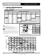
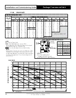
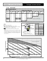
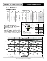
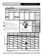
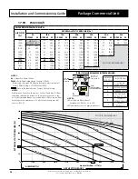
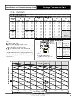
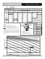
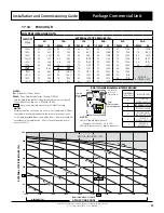
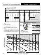
17.03. PCG203U/V
FAN PERFORMANCE DATA
AIRFLOW
(l/s)
EXTERNAL STATIC PRESSURE (Pa)
50
75
100
125
150
175
200
% PWM
W
% PWM
W
% PWM
W
% PWM
W
% PWM
W
% PWM
W
% PWM
W
900
52
357
53
395
55
438
58
481
62
522
65
563
69
608
925
53
371
55
420
58
459
62
510
65
549
67
586
70
641
950
55
402
58
446
62
489
65
533
67
577
70
624
75
669
975
58
423
62
476
65
515
67
553
70
608
74
666
1000
62
454
65
499
68
547
70
593
73
641
75
682
1025
65
476
68
533
70
571
73
625
76
672
80
719
1050
68
511
70
557
73
607
76
659
79
708
85
755
1075
70
534
73
586
76
640
79
697
82
740
1100
73
570
76
624
79
680
82
728
84
750
MOTOR / BLOWER LIMIT
1125
76
604
79
656
82
712
84
750
85
769
1150
79
644
82
694
85
749
88
806
NOTES:
Performance Fan Curve shown is at Dry Coil Condition. Airflow
should be reduce with respect to the moisture content in the
air. All data provided does not include filters. Please review filter
manufacturer for application. 2.5 m/s face velocity point will
occur at 1200
l/s.
NOTES:
W
= Indoor Fan Power, Watts
PWM
= Pulse Width Modulation Setting, % PWM
(Adjustable through CPI3-2 Board located in electrical panel).
Factory PWM Setting = 68 % PWM for 100 Pa.
- Data in the box indicates Factory Default Setting.
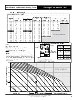
JUMPER PIN
POSITION
INDOOR FAN
A
NOT USED
B
NOT USED
C
PCG153U/V
D
PCG173U/V
E
PCG203U/V
F
PCG233U/V
(CPI3-2) RESIDENTIAL PWM INTERFACE BOARD
NOTES:
LED will show PWM without %.
Example: 68% PWM = 68 in LED.
LED adjustments are in 1 digit increments.
CPI 3
23787-3
C3
DISP2 DISP1
MODEL
A
B
C
D
E
F
ADJUST
V2
C2
P3
C1
+
+
P1
V2.1
U4
U3
R11
R12
R13
R14
R15
C5
D3
R3
R4
C7
R2
R1
RV1
TRA-0100-R
D1
D2
P5
INPUT
R10
C8
P6
GND
0 - 10
V
PWM1 OUT
DAMAGE DUE TO
INCORRECT WIRING
VOIDS WARRANTY
CPI3-2
S/N: XXXXXXXX
IF
ON/OFF
IF
PWR
240VAC IN
ActronAir
LED FAN
PWM
DISPLAY
JUMPER PIN
SET AS PER
TABLE BELOW
PWM
ADJUSTMENT
(POTENTIOMETER)
FAN CURVE
0
25
50
75
100
125
150
175
200
225
250
900
925
950
975
1000
1025
1050
1075
1100
1125
1150
AIRFLOW (l/s)
Nominal Airflow = 1000 l/s
250
225
200
175
150
125
100
75
50
25
0
EXTERNAL S
TA
TIC PRE
SSURE (P
a)
900
925
950
975
1000
1025
1050
1075
1100
1125
1150
APPLICATION RANGE
55% PWM
60% PWM
70% PWM
75% PWM
85% PWM
80% PWM
50% PWM
68% PWM
90% PWM
MOTOR / BLOWER LIMIT
65% PWM

