Installation and Commissioning Guide
Package Commercial Unit
21
Installation and Commissioning Guide - Package Commercial Unit
Doc. Part No. 0525-055 Ver. 9 220308
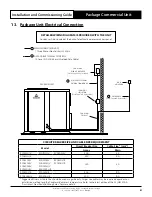
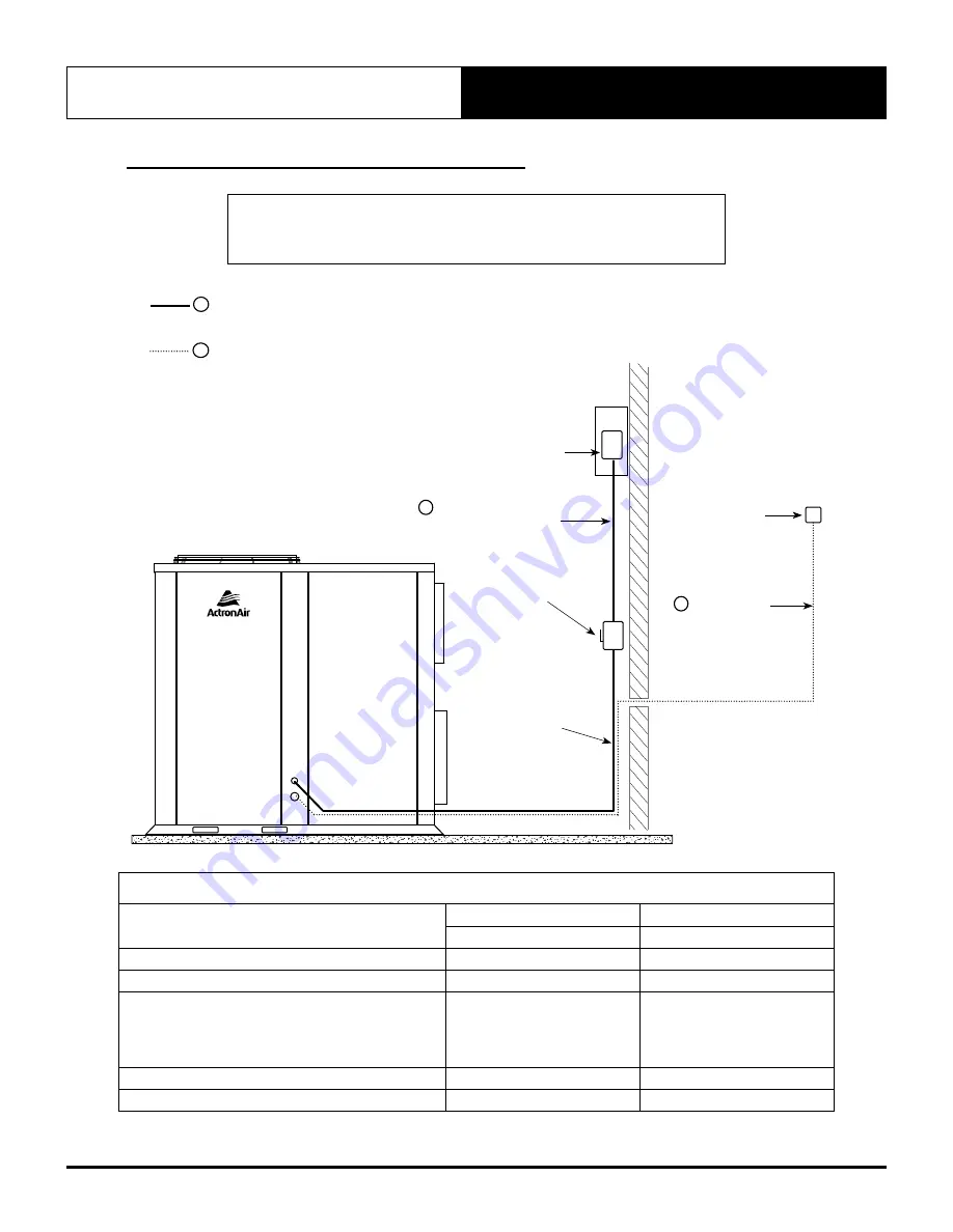
13. Package Unit Electrical Connection
DETAILED WIRING DIAGRAM IS PROVIDED WITH THE UNIT
Condenser Side: Located at the back of electrical/compressor access panel.
MAINS WIRING (400 VAC)
( Three Phase +Earth) 50Hz
DATA CABLE TO WALL CONTROL
(2 Core 14/0.20 0.44mm Shielded Data Cable)
1
2
WALL
CONTROL
SUB-MAINS
CIRCUIT BREAKER
(Field Supplied by Installer)
DATA CABLE
(Field Supplied by Installer)
2
MAIN SUPPLY FROM
DISTRIBUTION BOARD
SUB-MAIN
TO UNIT
SUB-MAINS
ISOLATOR
(Field Supplied by Installer)
1
PACKAGE UNIT
CIRCUIT BREAKER SIZE AND CABLE SIZE REQUIREMENT
Model
Circuit Breaker Size
Cable Size * (mm
2
)
Amps
Main
PCG153U/V
PCG173U/V
PCG203U/V
20.0
2.5
PCG233U/V
25.0
4.0
PCG260U/V
PCG290U/V
PCA300U/V
PCA330U/V
PCG330U/V
PCA340U/V
PCG340U/V
PKA300T-L/R
PCG290L/R
PCG300L/R
32.0
6.0
PCG330L/R
PCG340L/R
40.0
10.0
PCG400U/V
PCG400L/R
50.0
10.0
* Suggested Minimum Cable Size should be used as a guide only. Larger size cables may be required dependent on
installation method, length of cables and ambient temperature. Refer to the latest edition of the AS/NZS 3000
“Australian / New Zealand Wiring Rules” for more details.

