
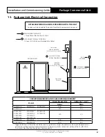
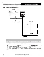
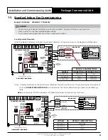


Installation and Commissioning Guide - Package Commercial Unit
Doc. Part No. 0525-055 Ver. 9 220308
Installation and Commissioning Guide
Package Commercial Unit
26
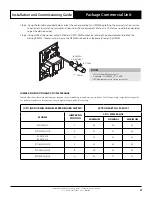
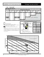
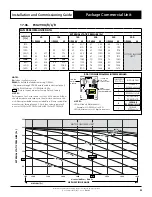
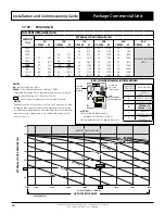
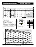
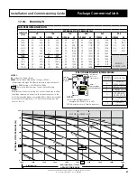
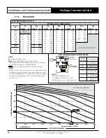
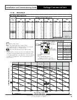
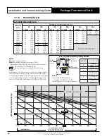
JUMPER PIN POSITION AND CPI3-2% PWM RANGE
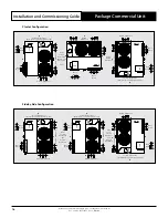
Table below shows factory default jumper position to corresponding air conditioning models to limit fan operating
range. Refer to specific fan performance data and fan curve on next page for factory default fan setting.
(CPI3-2) PWM INTERFACE BOARD
ACTRON PART NO. 2020-103
MODELS
JUMPER PIN
POSITION
CPI3-2 % PWM RANGE
MINIMUM
NOMINAL
MAXIMUM
NOT USED
A
-
-
-
NOT USED
B
-
-
-
PCG153U/V
C
64
84
98
PCG173U/V
D
66
88
99
PCG203U/V
E
52
68
88
PCG233U/V
F
46
67
99
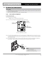
16.02. PCG260U/V to PCG400U/V/L/R add PKA300T-L/R
Fan Adjustment Procedure:
Step 1. Locate CPI Fan Controller :
Package Systems - Outdoor Section Electrical Pane
Step 2. Turn ON the unit through the installed wall controller or thermostat.
CPI 3
23787-3
C3
DISP2 DISP1
MODEL
A
B
C
D
E
F
ADJUST
V2
C2
P3
C1
+
+
P1
P2
V1.0
U4
U3
R11
R12
R13
R14
R15
C5
D3
R3
R4
C7
R2
R1
RV1
TRA-0100-R
D1
D2
P5
TX1
240VAC OUT
INPUT
R10
C8
P6
GND
0 - 10
V
PWM1 OUT
PWM2 OUT
P4
DAMAGE DUE TO
INCORRECT WIRING
VOIDS WARRANTY
CPI3-
1
S/No:
11G1
2276
IF
ON/OFF
IF
PWR
240VAC IN
ActronAir
LED FAN
PWM DISPLAY
(CPI3-1)
COMMERCIAL PWM INDOOR BOARD
PWM
ADJUSTMENT
(POTENTIOMETER)
JUMPER PIN
SET AS PER
TABLE BELOW