background image

25

Chapter 2

Setting Up the Gateway

9.

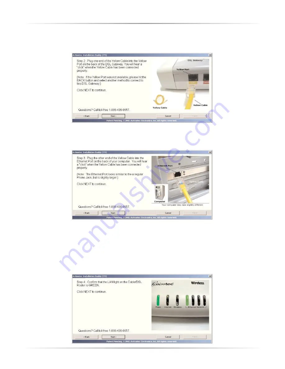
When the next window appears, plug one end of the 

Yellow (Ethernet) Cable

into the 

Yellow Port

on the back of the Gateway, then click 

Next

.

10.

Another window appears. Plug the other end of the 

Yellow (Ethernet) Cable

into an 

Ethernet port

on the back of the computer, then click 

Next

.

Note

: An Ethernet port looks similar to a phone port, but is

slightly bigger.

11.

When the next window appears, confirm the 

Power

and one of the 

Ethernet

Lights

on the Gateway 

glows steadily green

. This may take up to 30 seconds.

Click 

Next

.

Summary of Contents for Wireless-Ready DSL Gateway

Page 1: ...User Manual Wireless Ready DSL Gateway ...

Page 2: ...3 Gateway Features 36 4 Advanced Setup 37 Accessing Advanced Setup 37 WAN IP Address 38 Wireless Settings 41 LAN IP Address 44 DHCP Server 44 Services Blocking 46 Website Blocking 47 VPN Pass Through 47 Remote Management 48 Port Forwarding 48 DMZ Hosting 50 Firewall 51 Dynamic Routing 51 NAT Network Address Translation 52 Static Routing 52 MAC Address Cloning 53 Status 54 5 Utilities 57 Web Activi...

Page 3: ...ifications 79 General 79 Wireless Operating Range 80 LED Indicators 80 Environmental 81 C Glossary 83 D Security Level Services Table 87 High Security Level 87 Medium Security Level 88 Low Security Level 88 E Non Windows System Setup 89 Classic 89 OS X 91 Connecting to the ISP 92 Notices 95 Regulatory Compliance Notices 95 Modifications 95 Limited Warranty 97 ...

Page 4: ...ess Ready DSL Gateway Power adapter Ethernet cable USB cable Installation CDs Quick start guide Warranty and registration card Minimum System Requirements Active DSL service Computer with an 10 Mbps or 10 100 Mbps Ethernet connection Microsoft Windows 95 Windows 98 Windows 98 Second Edition SE Windows Millennium Edition Me Windows NT 4 0 Windows 2000 Windows XP Mac OS 7 1 Mac OS 8 0 Mac OS 9 0 or ...

Page 5: ...high perform ance products If you need assistance the Actiontec Technical Support Department is available every day from 6 A M to 11 P M MST to provide professional support Actiontec Electronics Inc 760 N Mary Avenue Sunnyvale CA 94085 Technical Support Phone 719 884 8300 E mail techsupp actiontec com Internet www actiontec com support ...

Page 6: ...Computers on page 22 Note The Installation Buddy is not supported on computers running Windows 95 and NT 4 0 Macintosh or Linux operating systems Connecting a Computer to the Gateway Connecting a computer to the Gateway for setup involves three basic steps initial setup plugging in the Gateway s Power Cord and connecting the Gateway to the computer Note The following procedures are for U S install...

Page 7: ...appears read the onscreen instructions select an option then click Next 3 The next window appears Read the instructions select First Computer by clicking on the check box then click Next 4 In the next window select the type of Gateway 1 Yellow Port or 4 Yellow Port then click Next ...

Page 8: ...hernet then click Next 6 The next window appears with information regarding Actiontec s 24 hour 7 day a week Technical Support If you have any problems call 1 888 436 0657 Click Next 7 The next window appears showing the items needed to set up the Gateway Click Next ...

Page 9: ...xt 9 When the next window appears get the Yellow Cable and connect one end to one of the Yellow Ports on the back of the Gateway then click Next 10 Another window appears Plug the other end of the Yellow Cable into an Ethernet port on the back of the computer then click Next Note An Ethernet port looks similar to a phone jack but is slightly larger ...

Page 10: ... Depending on the country the picture in the previous fig ure may or may not reflect the type of power cord supplied 12 The next window appears Plug the smaller end of the Power Cord into the Black Port on the back of the Gateway then click Next 13 When the next window appears plug the larger end of the Power Cord into a Power Outlet then click Next ...

Page 11: ...teway glows steadily green This may take up to 30 seconds Click Next 15 The following window appears Get the Black DSL Cable and plug one end into the Green Line Port on the back of the Gateway then click Next 16 When the next window appears plug the other end of the Black DSL Cable into the Phone Jack nearest to the computer then click Next ...

Page 12: ...een check all connections to the Gateway If all connections are plugged in properly call your DSL service provider The Gateway is connected to a computer via Ethernet Next install the filters as described in Installing Filters on page 15 Connecting Via USB 1 Insert Disk 1 Installation Buddy CD in the CD ROM drive of the computer The Installaton Buddy will start automatically Wait until the followi...

Page 13: ...appears read the onscreen instructions select an option then click Next 3 The next window appears Read the instructions select First Computer by clicking on the check box then click Next 4 In the next window select the type of Gateway 1 Yellow Port or 4 Yellow Port then click Next ...

Page 14: ... click Next 6 The next window appears with information regarding Actiontec s 24 hour 7 day a week Technical Support If you have any problems call 1 888 436 0657 Click Next 7 The next window appears with information regarding the items needed to set up the Gateway Click Next ...

Page 15: ...ears get the Purple Cable and connect the square end to the Purple Port on the back of the Gateway then click Next 10 Another window appears Plug the rectangular end of the Purple USB Cable into a USB port on the front or back of the computer then click Next Note A USB port is shaped like a thin rectangle about 1 4 inch by 1 2 inch and may be vertically or horizontally oriented ...

Page 16: ...e Depending on the country the picture in the previous fig ure may or may not reflect the type of power cord supplied 12 The next window appears Plug the smaller end of the Power Cord into the Black Port on the back of the Gateway then click Next 13 When the next window appears plug the larger end of the Power Cord into a Power Outlet then click Next ...

Page 17: ...steadily green This may take up to 30 seconds Click Next 15 The following window appears Get the Black DSL Cable and plug one end into the Green Line Port on the back of the Gateway then click Next 16 When the next window appears plug the other end of the Black DSL Cable into the Phone Jack nearest to the computer then click Next ...

Page 18: ... DSL service provider The Gateway is connected to a computer via USB Next install the phone filters as described in Installing Filters below Installing Filters Filters allow the use of the phone while online All phones and other devices answering machines fax machines etc using the same line i e using the same phone number as the DSL line must have a filter installed To install a filter follow the...

Page 19: ...erning home security alarms then click Next 2 When the next window appears unplug all phone cords from their respective phone jacks then click Next Caution Do not unplug the black DSL cable from the phone jack near your computer 3 Plug a filter in every phone jack using the same number as the DSL line then click Next ...

Page 20: ...the next window read the instructions Plug the loose end of the existing phone cord into a filter keeping the other end connected to the device phone fax machine answering machine etc Click Next 5 Answer the question Do you have a phone next to your computer in the following window by clicking Yes or No then click Next ...

Page 21: ...wered Yes the following window appears Unplug the phone cord connected to the phone from its phone jack in the wall the click Next Caution Do not unplug the black DSL cable from the phone jack near your computer 7 When the next window appears plug the loose end of the phone cord into a filter Caution Do not connect a phone filter to the black DSL cable ...

Page 22: ...igura tion in the picture below if the first computer is connected via USB if the first computer is connected via Ethernet the yellow cable will be plugged into one of the yellow ports Click Next Next go to Setting Up the DSL Connection below Setting Up the DSL Connection After connecting the Gateway and installing filters the DSL connection must be configured To do this 1 When the following windo...

Page 23: ...he next window select the type of setup implementation then click Next Basic Setup 1 If Basic Setup was chosen the following window appears Enter the appro priate user name and password in the text boxes If no user name and pass word are needed click on the check box next to My ISP does not require this information Click Next ...

Page 24: ...window appears after the Gateway is successfully set up Click Finish to exit the Installation Buddy The first computer is configured to use the Gateway To connect additional com puters go to Connecting Additional Computers on page 21 Advanced Setup 1 If Advanced Setup was chosen select the type of connection then click Next ...

Page 25: ...nal Computers To connect additional computers to the Gateway select the type of connection then follow the instructions Connecting Via Ethernet 1 Insert Disk 1 Installation Buddy CD in the CD ROM drive of the comput er The Installaton Buddy will start automatically Wait until the following screen appears read the onscreen instructions select a country then click Next 2 When the following screen ap...

Page 26: ...ons select Addtional Computer by clicking on the check box then click Next 4 The next window appears Select the type of Gateway 1Yellow Port or 4 Yellow Ports by clicking on the appropriate check box then click Next 5 In the next window select Wired USB or Ethernet then click Next ...

Page 27: ...rnet then click Next 7 The next window appears with information regarding Actiontec s 24 hour 7 day a week Technical Support If you have any problems call 1 888 436 0657 Click Next 8 The following window appears Get the Yellow Ethernet Cable from the DSL Quick Start Kit then click Next ...

Page 28: ... 10 Another window appears Plug the other end of the Yellow Ethernet Cable into an Ethernet port on the back of the computer then click Next Note An Ethernet port looks similar to a phone port but is slightly bigger 11 When the next window appears confirm the Power and one of the Ethernet Lights on the Gateway glows steadily green This may take up to 30 seconds Click Next ...

Page 29: ... Click Finish The Gateway is connected to a computer via Ethernet Connecting Via USB 1 Insert Disk 1 Installation Buddy CD in the CD ROM drive of the comput er The Installaton Buddy will start automatically Wait until the following screen appears read the onscreen instructions select a country then click Next ...

Page 30: ...tions select an option then click Next 3 The next window appears Read the instructions select Addtional Computer by clicking on the check box then click Next 4 The next window appears Select the type of Gateway 1Yellow Port or 4 Yellow Ports by clicking on the appropriate check box then click Next ...

Page 31: ...ext window select Wired USB or Ethernet then click Next 6 In the next window select USB then click Next 7 The next window appears with information regarding Actiontec s 24 hour 7 day a week Technical Support If you have any problems call 1 888 436 0657 Click Next ...

Page 32: ...Quick Start Kit then click Next 9 When the next window appears plug square end of the Purple USB Cable into the Purple Port on the back of the Gateway then click Next 10 Another window appears Plug the other end of the Yellow Ethernet Cable into an Ethernet port on the back of the computer then click Next ...

Page 33: ...ertically or horizontally oriented 12 When the next window appears confirm the Power and Internet 4 Yellow Port model or Power and USB 1 Yellow Port model glows steadily green This may take up to 30 seconds Click Next 13 The Gateway connects and then the final window appears Click Finish The Gateway is connected to a computer via Ethernet ...

Page 34: ...ddy will start automatically Wait until the following screen appears read the onscreen instructions select a country then click Next 2 When the following screen appears read the onscreen instructions select an option then click Next 3 The next window appears Read the instructions select Addtional Computer by clicking on the check box then click Next ...

Page 35: ...by clicking on the appropriate check box then click Next 5 In the next window select Wireless then click Next 6 The next window appears Read and follow the onscreen instructions To fin ish connecting the Gateway wirelessly to the computer insert the CD that come with the PC Card into the computer s CD ROM drive and run the client setup ...

Page 36: ...connect the Gateway to the ISP as well as an overview of the Gateway s LEDs and switches Basic Setup To configure the gateway for basic operation 1 Open the Web browser In the address bar enter http 192 168 0 1 then press Enter on the keyboard 2 The Main Menu screen appears Select Setup Configuration 4 ...

Page 37: ...in the Set Up Configuration screen then click Begin Basic Setup 4 In the next window follow the onscreen instructions then click Next 5 In the next window select the type of connection by clicking on the circle next to PPPoA or PPPoE If unsure about the selection contact the ISP ...

Page 38: ...ck Save and Restart in the Save and Restart screen 8 The Congratulations screen appears The Gateway is successfully configured The power LED flashes rapidly while the Gateway restarts then glows steadily green when fully operational The Gateway is now configured and users can start surfing the Web If an error stating the Web browser was unable to connect to the Internet appears check the configura...

Page 39: ...Gateway has suffered a critical error and technical support should be contacted Internet LED When the Internet LED glows steadily the Gateway is connected to the ISP Wireless LED When the Wireless LED glows steadily the Gateway is ready for wireless networking Ethernet Network LED The Ethernet Network LEDs glow when a network link is established with a computer A flashing LED signifies network tra...

Page 40: ...dvanced Setup To access the Advanced Setup configuration screens follow these instructions 1 Open the Web browser In the address bar enter http 192 168 0 1 then press Enter on the keyboard 2 The Main Menu screen appears Select Setup Configuration 3 In the Set Up Configuration screen read the instructions then select Advanced Setup from the menu on the left side 5 ...

Page 41: ...ote Click Save and Restart on the bottom left hand side of the screen after finishing the configuration of one or more of the Advanced Setup settings WAN IP Address Selecting WAN IP Address in the Advanced Configuration screen generates the WAN IP Address screen WAN IP Address allows manual set up of the IP address of the Gateway There are three ways to do this Obtain an IP Address through PPPoE P...

Page 42: ...ction type click Next to continue configuring the connection Transparent Bridging Select this option to use the Gateway as a transparent bridge This option should only be used if the Gateway is being used as a Modem to connect one computer to the Internet via a DSL connection When the Gateway is being used as a transpar ent bridge it does not provide any firewall security Note If more than one com...

Page 43: ...rnet Service Provider ISP Obtain an IP Through DHCP Select this option used for cable modem configurations without a Static IP assigned by an ISP to allow the modem to query the Internet Service Provider ISP and receive IP address and routing information Some ISPs need to authenticate their end users with a Host Name and or Domain Name If this is the case check with the ISP for a host name and dom...

Page 44: ... with the Subnet Mask and Default Gateway Address also provided by the ISP in the Broadband Connection via Static IP Address screen If required to provide a Host Name and Domain Name enter them here as well Wireless Settings Selecting Wireless Settings in the Advanced Configuration screen generates the Wireless Settings screen Modify the wireless capabilities of the Gateway here ...

Page 45: ... the Actiontec 802 11b Wireless PC Card the ESSID value must be the same as the SSID value Channel Channel assigns the frequency band at which the Gateway communicates In the United States use channels 1 11 The factory default value is set to 1 Wireless Equivalent Privacy Wireless Equivalent Privacy WEP is an encryption method used with the 802 11b standard to ensure data security over wireless ne...

Page 46: ...me keys are entered in the computer s wireless encryption scheme 128 bit WEP 128 bit WEP requires one key of 13 hexadecimal pairs A hexadecimal digit con sists of alphanumeric characters ranging from 0 9 or A F An example of a 128 bit WEP key is 3D 44 FE 6C A1 EF 2E D3 C4 21 74 5D B1 To create a 128 bit WEP key enter 13 hexadecimal digit pairs in the Key text box After activating 128 bit WEP on th...

Page 47: ...ault factory setting 192 168 0 1 Note If the Gateway s LAN IP Address is modified verify the DHCP Server range is within the same subnet For more infor mation see DHCP Server Configuration DHCP Server Selecting DHCP Server in the Advanced Configuration screen generates the DHCP Server screen The Gateway has a built in DHCP Dynamic Host Configuration Protocol server that automatically assigns a dif...

Page 48: ...gs 192 168 0 254 The beginning and ending IP addresses define the IP address range of the Gateway If the default values are left intact the Gateway supplies a unique IP address between 192 168 0 2 and 192 168 0 254 to each computer on the net work Note that the first three groups of numbers of the addresses are identical this means they are on the same subnet The IP address of the Gateway must be ...

Page 49: ... privileges Web FTP Newsgroups etc for the computers on the network 1 Enter the computer s IP address in the Enter IP Address text box 2 Select the Internet service s to be blocked 3 Click Add to enter the computer s IP address in the Blocked IP Address List text box 4 To remove blocked services select the computer s IP address in the Blocked IP Address List text box and click Remove Netmeeting To...

Page 50: ... blocked Web site address will be displayed in the Blocked Website List text box and will not be available to com puters on the network To remove a blocked Web site click on it in the Blocked Website List then click Remove VPN Pass Through Selecting VPN Pass Through in the Advanced Configuration screen generates the VPN Pass Through screen To set up Virtual Private Networking VPN using IPSec L2TP ...

Page 51: ...ted the admin istrator password must be set To do this go to the Basic Setup screen and select Change Admin Password Follow the instruc tions in the subsequent screens Port Forwarding Selecting Port Forwarding in the Advanced Configuration screen generates the Port Forwarding screen Port forwarding allows certain programs to bypass the Gateway s built in firewall allowing access to parts of the ne...

Page 52: ...n IP addresses to access forwarded ports Enter the port range of the forwarded ports in the Remote IP Port Range text boxes enter the IP address to be allowed access in the Remote IP Address text box then click Add The active forwarded ports will appear in the List of Forwarded Ports text box To deactivate a forwarded port select it from the List of Forwarded Ports text box then click Remove ...

Page 53: ...hosting is used to support online gaming and Internet conferencing services These programs usually require multiple open ports making the network accessi ble from the Internet DMZ hosting symbolically places the DMZ host computer outside of the Gateway s network Access to the network resources while DMZ hosting is active is blocked Actiontec recommends activating DMZ hosting only as long as necess...

Page 54: ...network See Appendix E for details concerning each level of security Dynamic Routing Selecting Dynamic Routing in the Advanced Configuration screen generates the Dynamic Routing screen If a router is set up behind the Gateway in the network configuration consult the documentation that came with the router to see what kind of Dynamic Routing is required then select the needed option ...

Page 55: ...o the Gateway to be accessed by outside parties Do not turn NAT off unless instructed to do so by the Internet Service Provider ISP Static Routing Selecting Static Routing in the Configuring the Advanced Settings screen gener ates the Static Routing screen Enter the addresses in their respective text boxes then click Add The address will appear in the Static Routing Table To remove an address high...

Page 56: ...ry networkable device Some Internet Service Providers ISP require a MAC address to validate a computer s permission to be on their net work If the ISP requires this information obtain the MAC address of the computer originally configured for the ISP see Appendix D for instructions to determine the computer s MAC address Enter the MAC address in the User Select WAN MAC Address text boxes in the MAC...

Page 57: ...s settings No settings other than connecting or disconnecting from the Internet can be changed from the Current Status screen In the left hand column there are other Status options available Routing Table WAN Status LAN Status and Active User List Click to generate the option of choice Routing Table Selecting Routing Table generates the Routing Table screen This screen displays on overview of the ...

Page 58: ...es a Current Status screen This screen displays on overview of the Gateway s WAN Wide Area Network connection LAN Status Selecting LAN Status generates the Lan Port Status screen This screen displays on overview of the Gateway s LAN Local Area Network port connections ...

Page 59: ... Manual Active User List Selecting Active User List generates the Active User List screen This screen dis plays a list of the users currently connected to the Gateway accessing the Internet with Network Address Translation NAT security activated ...

Page 60: ...ity log can be viewed the DSL settings changed the Gateway s factory default settings restored and the Gateway s firmware upgraded Web Activity Log The Web Activity Log provides information about the Web sites each computer on the Gateway s network has visited To access the Web Activity Log select Web Activity Log from the Utilities screen 6 ...

Page 61: ...gs select Restore Default Settings from the Utilities screen When the Restore Default Settings screen appears click Restore Default Settings Any changes made to the Gateway s settings will be lost and the factory default settings will be restored During this process the Gateway s power LED flashes and the Gateway is disabled Warning Do not unplug the power adapter from the Gateway during the Resto...

Page 62: ...ard drive of the computer 2 Double click on the upgrade file named upgrade exe 3 Enter the IP address of the Gateway and click Start The upgrade process begins Warning Do not unplug the power adapter from the Gateway during the Upgrade Firmware process Doing so may result in permanent damage to the Gateway 4 After the upgrade is complete unplug the power adapter from the Gateway then plug it back ...

Page 63: ...60 Actiontec Wireless Ready DSL Gateway User Manual ...

Page 64: ...n IP address within the range it will not connect to the Gateway Ensure the Subnet Mask address is set to 255 255 255 0 by clicking Status in the Main Menu screen Cannot Connect to the Internet Ensure both ends of the power adapter and network cables are properly connected and the status LEDs on the front panel are working properly If running Windows 98 check the computer s TCP IP settings Select ...

Page 65: ...dress Verify all the computers are working properly Ensure the IP settings are correct Ensure the Gateway is on and connected properly Verify the Gateway s settings are the same as the computer by clicking Status in the Main Menu screen Check the cable DSL modem by attempting to connect to the Internet ...

Page 66: ...he Gateway are on the same subnet To set up static IP on a computer select the operating system and follow the instructions Note The following procedures are based on the Gateway s fac tory default IP address If the Gateway s IP address has been changed enter the new IP address when instructed to enter an IP address Windows 98 and 98 SE 1 From the desktop click on the Start button in the lower lef...

Page 67: ...64 Actiontec Wireless Ready DSL Gateway User Manual 3 Another menu appears Select Control Panel 4 When the Control Panel window appears double click Network ...

Page 68: ... TCP IP Properties window appears Select IP Address 7 In the IP Address tab make sure the the circle next to Specify an IP Address is selected When active a black dot appears in the circle If the circle already contains a black dot leave it alone 8 Enter the following numbers in the IP Address text box 192 168 0 2 Do not include the periods they are automatically entered ...

Page 69: ...appears 11 In the Network window click OK The Network window disappears 12 The System Settings Change window appears asking whether the computer should be restarted Click Yes The computer restarts It is now set up with a static IP address allowing the user to access the Modem s Advanced Setup utility Windows Me 1 From the desktop click on the Start button in the lower left corner 2 From the menu t...

Page 70: ...67 Appendix A Setting Up Static IP Address 3 Another menu appears Select Control Panel 4 When the Control Panel window appears double click Network ...

Page 71: ...6 The TCP IP Properties window appears Click IP Address 7 In the IP Address tab make sure the the circle next to Specify an IP Address is selected When active a black dot appears in the circle If the circle already contains a black dot leave it alone 8 Enter the following numbers in the IP Address text box 192 168 0 2 Do not include the periods they are automatically entered ...

Page 72: ...nnection to network media click on it to uncheck the box 12 In the Network window click OK The Network window disappears 13 The System Settings Change window appears asking whether the computer should be restarted Click Yes The computer restarts It is now set up with a static IP address allowing the user to access the Modem s Advanced Setup utility Windows 2000 1 From the desktop click on the Star...

Page 73: ...70 Actiontec Wireless Ready DSL Gateway User Manual 3 Another menu appears Select Control Panel 4 When the Control Panel window appears double click Network and Dial up Connections ...

Page 74: ... may be displayed after the Local Area Connection If there is more than one Local Area Connection listed locate the one that corre sponds to the network card installed in the computer by finding the name of the network card in the Device Name column 6 The Local Area Connection Status window appears Select General then click Properties ...

Page 75: ... Protocol TCP IP 9 The Internet Protocol TCP IP Properties window appears 10 In the General tab make sure the the circle next to Obtain an IP Address automatically is selected When active a black dot appears in the circle If the circle already contains a black dot leave it alone 11 Enter the following numbers in the IP Address text box 192 168 0 2 Do not include the periods they are automatically ...

Page 76: ... OK The Local Area Connection Properties window disappears 15 Click Close in the Local Area Connection Status window The window disap pears 16 Close the Network and Dial up Connections window by clicking on the x button at the upper right corner of the window The computer is now set up with a static IP address allowing the user to access the Modem s Advanced Setup utility Windows XP 1 From the des...

Page 77: ...74 Actiontec Wireless Ready DSL Gateway User Manual 3 Another menu appears Select Control Panel 4 When the Control Panel window appears double click Network Connections ...

Page 78: ...e displayed after the Local Area Connection If there is more than one Local Area Connection listed locate the one that corresponds to the network card installed in your computer by finding the name of the network card in the Device Name column 6 The Local Area Connection Status window appears Select General then click Properties ...

Page 79: ...hecked are used by this connection list box double click Internet Protocol TCP IP 9 The Internet Protocol TCP IP Properties window appears 10 In the General tab make sure the the circle next to Obtain an IP Address automatically is selected When active a black dot appears in the circle If the circle already contains a black dot leave it alone ...

Page 80: ...ed 13 Click OK The Internet Protocol TCP IP Properties window disappears 14 In the Local Area Connection Properties window click OK The Local Area Connection Properties window disappears 15 Click Close in the Local Area Connection Status window The window disappears 16 Close the Network and Dial up Connections window by clicking on the x button at the upper right corner of the window The computer ...

Page 81: ...78 Actiontec Wireless Ready DSL Gateway User Manual ...

Page 82: ... Standards IEEE 802 3 10BaseT IEEE 802 3u 100BaseTX IEEE 802 11b Wireless G dmt G lite t1 413 RFC 1483 2364 2516 Protocol CSMA CD WAN Full rate DSL modem LAN GS204AD9 01 10 100 RJ 45 switched ports 4 USB port 1 GS404AD9 01 10 100 RJ 45 port 1 USB port 1 Expansion PCMCIA expansion slot 2 B ...

Page 83: ...Category 5 USB Wireless Operating Range If used Indoors Up to 30M 100 ft 11 Mbps Up to 50M 165 ft 5 5 Mbps Up to 70M 230 ft 2 Mbps Up to 91M 300 ft 1 Mbps Outdoors Up to 152M 500 ft 11 Mbps Up to 270M 885 ft 5 5 Mbps Up to 396M 1300 ft 2 Mbps Up to 457M 1500 ft 1 Mbps Topology Star Ethernet LED Indicators 4 port Power Internet Wireless LAN USB 1 port Power Internet Wireless Ethernet Network ...

Page 84: ... 12V DC 1 2 A Certifications FCC Class B FCC Class C part 15 68 CE Mark Commercial UL Operating Temperature 0º C to 40º C 32ºF to 104ºF Storage Temperature 20ºC to 70ºC 4ºF to 158ºF Operating Humidity 10 to 85 non condensing Storage Humidity 5 to 90 non condensing ...

Page 85: ...82 Actiontec Wireless Ready DSL Gateway User Manual ...

Page 86: ...ocol A protocol designed to automatically assign an IP address to every computer on a network DNS Domain Name System Server Address Allows Internet host computers to have a domain name and one or more IP addresses A DNS server keeps a database of host computers and their respective domain names and IP addresses so that when a user enters a domain name into a Web browser the user is sent to the pro...

Page 87: ...Provider A business that connects individuals or businesses to the Internet LAN Local Area Network A group of computers and devices connected together in a relatively small area such as a house or an office A home network is considered a LAN MAC Media Access Control Address The hardware address of a device connected to a network NAT Network Address Translation Allows all computers on a network to ...

Page 88: ...a Network A network connecting computers located in separate areas i e different build ings cities countries The Internet is a WAN WECA Wireless Ethernet Compatibility Alliance An industry group that certifies cross vender interoperability and compatibility of IEEE 802 11b wireless networking products and promotes the standard for enterprise small business and home environments WLAN Wireless Local...

Page 89: ...86 Actiontec Wireless Ready DSL Gateway User Manual ...

Page 90: ...he Gateway s network can not access a computer on the network via the http service in this case no comput ers on the network can be used as a Web server i e hosting a Web site accessible to outside users However since yes is listed in the Out column all computers on the Gateway s network can access the Internet via the http port If Basic Security is selected in the Firewall screen firewall filteri...

Page 91: ...op3 110 no yes nntp 119 no yes real audio video 7070 yes no icmp n a no yes H 323 1720 no yes T 120 1503 no yes SSH 22 no yes Low Security Level Service Port In Out http 80 no yes dns 53 yes yes ftp 21 no yes telnet 23 no yes smtp 25 no yes pop3 110 no yes nntp 119 no yes real audio video 7070 yes no icmp n a yes yes H 323 1720 yes yes T 120 1503 yes yes SSH 22 yes yes ...

Page 92: ... Note When installing any software consult the user manual and help files supplied with the software for detailed information Actiontec provides the following information as a guideline only Classic To configure the Router Open Transport 2 5 2 or above must be loaded on the computer 1 Click Apple Control Panels then TCP IP E ...

Page 93: ...om the Configure drop down list 6 Ensure the Use 802 3 option is not checked 7 Disregard any addresses in the IP Address text boxes They will be reacquired when the first connection is made 8 Click Options and when the TCP IP Options window appears select Active Ensure the Load only when needed option is not checked then click OK 9 Close the TCP IP window and when prompted to save changes click Sa...

Page 94: ...ple Menu The Network window appears 2 Select Built In Ethernet from the Show drop down list 3 Select TCP IP and from the Configure drop down list select Using DHCP 4 Click Apply Now and close the System Preferences application The TCP IP settings are configured Next go to Connecting to the ISP on page 86 ...

Page 95: ...ng to the ISP 1 Open the Web browser In the address bar enter http 192 168 0 1 then press Enter on the keyboard 2 The Main Menu screen appears Select Setup Configuration 3 In the Set Up Configuration screen select Non Windows Setup from the menu on the left side ...

Page 96: ...ng the Internet Service Provider ISP Worksheet provid ed by the ISP enter the information in the appropriate text boxes If no worksheet has been provided contact the ISP 5 Click Save and Restart at the bottom of the Actiontec DSL Modem Setup Page screen The Gateway will be ready to use when the Power and Internet LEDs stop blinking ...

Page 97: ...94 Actiontec Wireless Ready DSL Gateway User Manual ...

Page 98: ...mined by turning the equipment off and on the user is encouraged to try to correct the interference by implementing one or more of the following measures Reorient or relocate the receiving antenna Increase the separation between the equipment and receiver Connect the equipment to an outlet on a circuit different from that to which the receiver is connected Consult the dealer or an experienced radi...

Page 99: ...require ments the antenna used for this transmitter must be installed to provide a separation distance of at least 20 cm from all persons and must not be co located or operating in conjunction with any other antenna or transmitter For questions regarding your product or the FCC declaration contact Actiontec Electronics Inc 760 North Mary Ave Sunnyvale CA 94086 United States Tel 408 752 7700 Fax 40...

Page 100: ...ctronics warrants the media con taining software against failure during the warranty period The only updates that will be provided are at the sole discretion of Actiontec Electronics and will only be available for download at the Actiontec Web site www actiontec com Actiontec Electronics sole obligation under this express warranty shall be at Actiontec Electronics option and expense to refund the ...

Page 101: ...paired or replaced item will be shipped to Customer at Actiontec Electronics expense not later than thirty 30 days after Actiontec Electronics receives the defective product Return the product to In the United States Actiontec Electronics Inc 760 North Mary Avenue Sunnyvale CA 94085 Actiontec Electronics shall not be responsible for any software firmware informa tion memory data or Customer data c...

Page 102: ...VISED OF THE POS SIBILITY OF SUCH DAMAGES AND LIMITS ITS LIABILITY TO REPAIR REPLACE MENT OR REFUND OF THE PURCHASE PRICE PAID AT ACTIONTEC ELECTRON ICS OPTION THIS DISCLAIMER OF LIABILITY FOR DAMAGES WILL NOT BE AFFECTED IF ANY REMEDY PROVIDED HEREIN SHALL FAIL OF ITS ESSENTIAL PURPOSE Disclaimer Some countries states or provinces do not allow the exclusion or limi tation of implied warranties or...

Page 103: ... Manual Governing Law This Limited Warranty shall be governed by the laws of the State of California U S A excluding its conflicts of laws and principles and excluding the United Nations Convention on Contracts for the International Sale of Goods ...

Reviews: