BusWorks
Model 903MB/902MB/901MB Network I/O Module User’s Manual Digital I/O
___________________________________________________________________________________________
- 22 -
COMMUNICATION INTERFACE SPECIFICATIONS
These units contain an isolated RS485 communication port
for the transmission of data.
Interface Standard:
RS-485. Communication with this module
is made over a 3-wire cable (D, D-bar, and Common).
Command/Response Protocol:
Standard Modbus RTU
protocol implemented as defined under “Modicon Modbus
Reference Guide” PI-MBUS-300 Rev J (reference
www.public.modicon.com
, search keyword PI-MBUS-300 to
obtain technical publication). See MODULE
CONFIGURATION for a review of Modbus and supported
commands.
Baud Rate:
Can be programmed for 2400, 4800, 9600 (Default
Mode), 14400, 19200, 28800, 38400, 57600, 76800, or
115200 bits per second.
Duplex:
Half Duplex only.
Parity:
Odd, Even, or None (Default Mode).
Stop Bits:
1 Stop Bit for Even or Odd parity, 1 or 2 Stop bits for
no parity.
Response Delay:
This is the minimum communication
turnaround delay that a module will wait before it sends its
response to a message from the host. It is applied in
addition to the inherent delay already present which varies
between models. It can be set from 0-65500 ticks, with 1 tick
equivalent to 1.085us. Some signal converters or
host/software systems cannot accept an immediate response
from the slave without additional delay. Note that you may
have to specify an amount of delay that is comparable to the
inherent delay already present before an effect can be
measured.
Module Address:
Can be set from 0-247 (01H-F7H). The
Default Mode address is 247 (F7H).
Network Capacity:
The Module has multi-drop capability for up
to 31 modules, plus host, without use of an RS485 repeater.
If a signal repeater is used for every 31 nodes, up to 247
modules may be networked, plus a host computer.
Communication Distance:
Up to 4000 feet without use of a
repeater. Distance can be extended with a signal repeater.
Default Communication Mode Parameters:
In this mode, the
module address is set to 247, the baud rate is set to
9600bps, the parity is set to none, and the number of stop
bits is set to 1 or 2 by pressing the DFT push-button on the
front of the module until the yellow Status LED flashes
ON/OFF. This is provided as a means to communicate with
a module when its internal address, baud rate, parity, and
stop bit settings are unknown. Exit the Default Mode by
pressing this button until the Status LED is NOT flashing
(constant ON or OFF), or by issuing a software or power-on
reset. Note that new communication parameters for module
address, baud rate, and parity do not take effect outside of
Default Mode until a software or power-on reset has
occurred.
Watchdog Timer:
A hardware watchdog timer is built into the
microcontroller that causes it to initiate a self reset if the
controller ever fails to return from an operation in a timely
manner or “locks up”. Additionally, an I/O watchdog timer
function is implemented that may be configured for timeout
periods up to 65534 seconds (18.2 hours). The I/O watchdog
timer will cause the status LED to blink rapidly, set a bit in the
Module Status Register, and optionally program the digital
outputs to a pre-defined state upon watchdog timeout. An
I/O watchdog timeout is cleared and the timer reinitiated via a
read or write to any port input/output channel.
Supported Modbus Commands:
The command & response
protocol for communicating with this module adheres to the
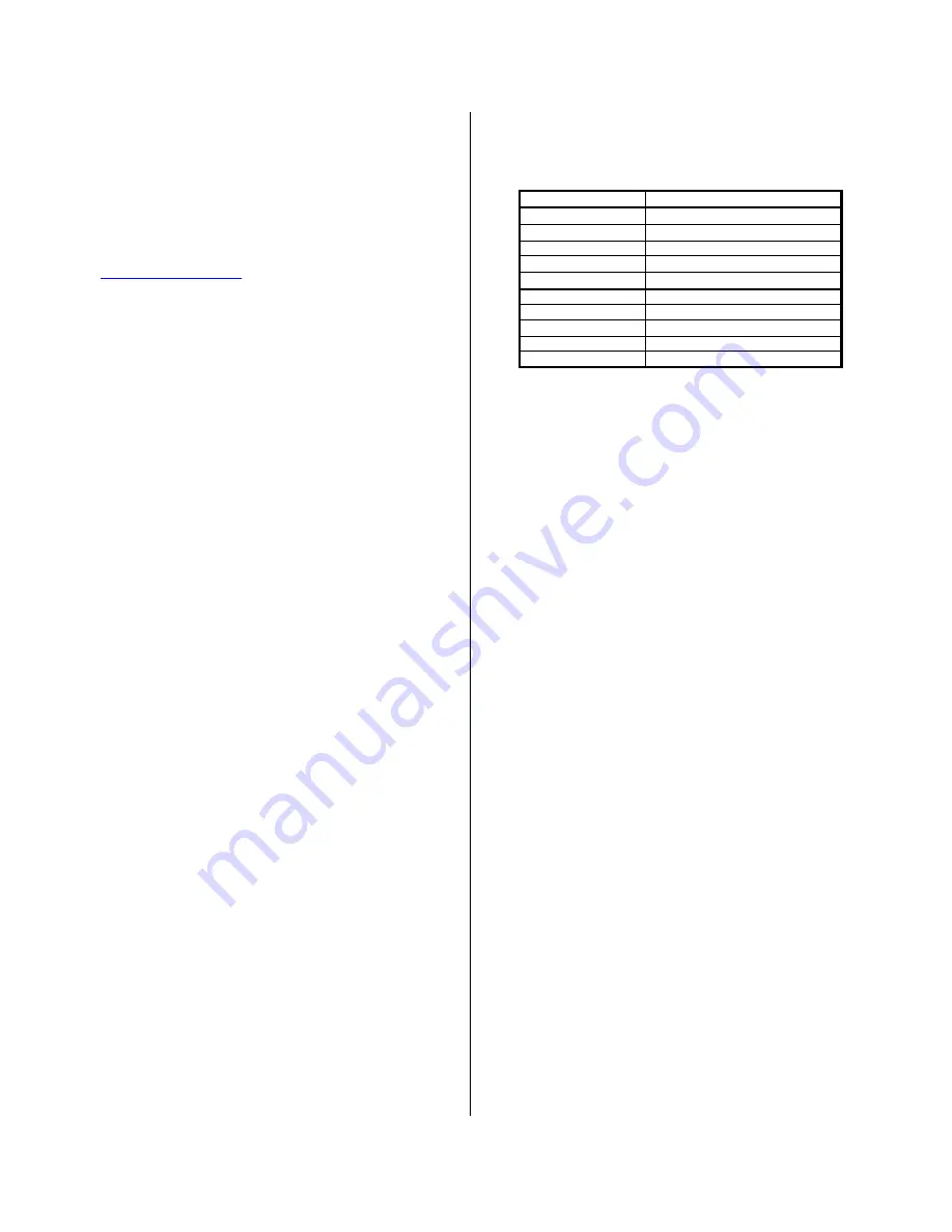
Modbus/RTU standard for the following Modbus Functions:
FUNCTION CODE
FUNCTION
01 (01H)
Read Coil (Output) Status
02 (02H)
Read Input Status
03 (03H)
Read Holding Registers
04 (04H)
Read Input Registers
05 (05H)
Force Single Coil (Output)
06 (06H)
Preset Single Register
08 (08H)
Reset Slave
15 (0FH)
Force Multiple Coils (Outputs)
16 (10H)
Preset Multiple Registers
17 (11H)
Report Slave ID
Refer to MODULE CONFIGURATION for detailed information
on these functions.
CONFIGURATION AND CONTROLS
Module Push Button (See Dwg. 4501-815 For Location):
Default (DEF) -
Push to engage or disengage the default
communication mode with baud rate set to 9600bps,
module address set to 247, and no parity selected. The
Status LED will flash ON/OFF when the module is in the
default mode. A module will leave the default mode
following a software or power-on reset (Status LED will
be OFF or constant ON).
LED Indicators:
Run (Green) -
Constant ON indicates power is applied and
unit is operating normally. Flashing ON/OFF indicates
unit is performing diagnostics (for two seconds following
power-up), or has failed diagnostics (after a few
seconds).
Status (Yellow) –
A slow flashing LED indicates the module
is in the Default Communication Mode. A rapid flashing
LED indicates a watchdog timeout has occurred. The
combination of timeout and default mode indication
resembles rapid flashing bursts.
Input/Output (Yellow) -
One per I/O point. OFF if output
switch is OFF, ON if output switch is ON. OFF if input is
high, ON if input is asserted low.
SOFTWARE CONFIGURATION
Units are fully reprogrammable via our user-friendly Windows
95/98
or NT
900MB Configuration Program (Model 900C-SIP).
Optionally, any software that supports the Modbus command/
response protocol may be used. See Drawing 4501-805.
The following transmitter attributes are configurable via the
900MB Configuration Software. Optionally, you may use the
Preset Single/Multiple Register functions to write configuration
data to the appropriate register(s) as required by your application
(see REGISTER MAP).


