background image

       BusWorks


Model 903MB/902MB/901MB Network I/O Module User’s Manual                                         Digital I/O 

       ___________________________________________________________________________________________ 

- 18 - 

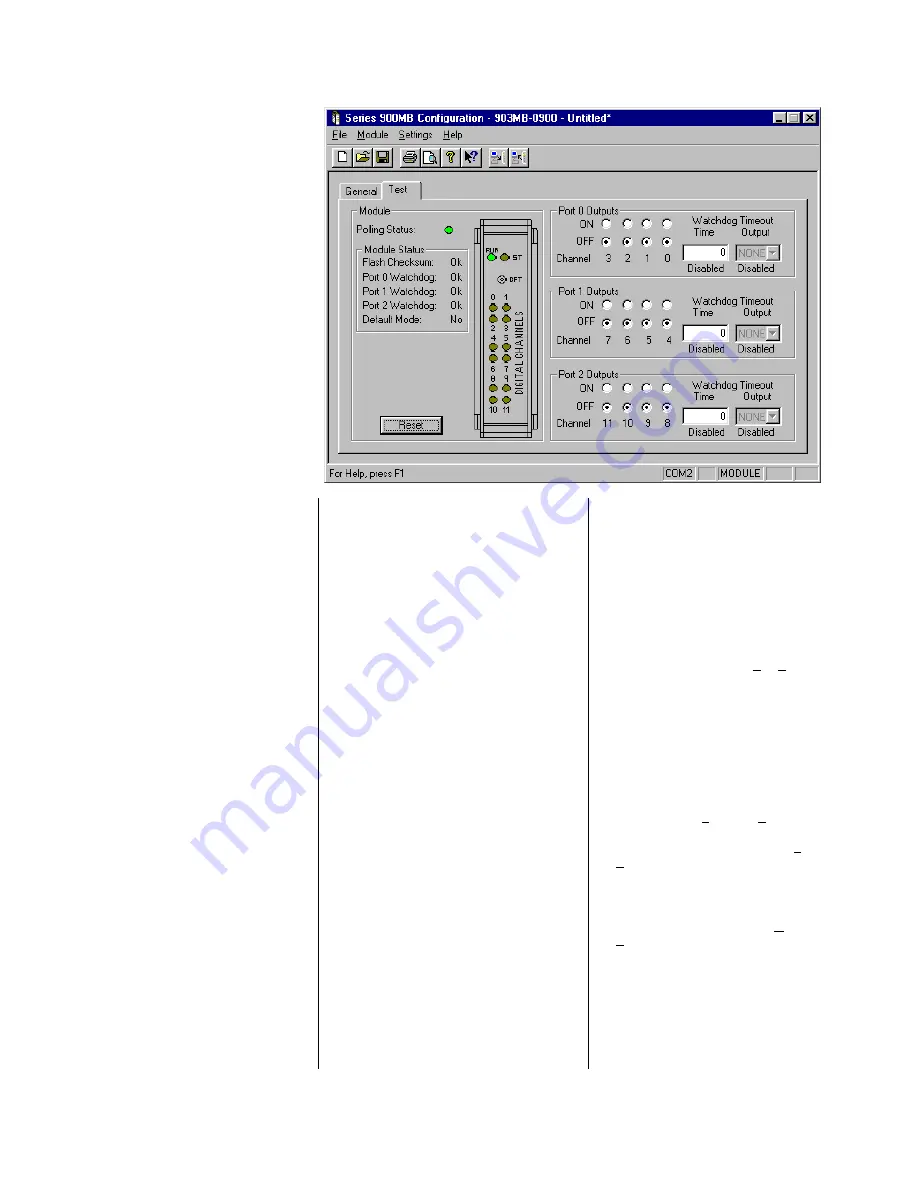
Testing Your Configuration 

 
The “Test” portion of this program 
allows you to monitor polling, module 
status flags, reset the module, control 
output states, and monitor input states. 

 
This page is also used to configure the 
port watchdog time and the timeout 
reset states for the port. 
 

Port I/O Watchdog Timer 

 
The right half of this screen allows you 
to configure the Port I/O Watchdog 
Timer.  A watchdog timeout is triggered 
if no channel read or write occurs for 
one or more port channels, within the 
timeout period specified.  A timeout is 
cleared and the timer reinitiated when a 
port channel read or write occurs.  Note 
that clearing a timeout does not return 
the outputs to their pre-timeout state.  
They will retain their current state until 
otherwise written. 


Use the port 0, 1, & 2 

“Timeout 

Output”

 scroll bar to select the timeout 

binary pattern to program the port 
outputs to following a timeout.  A pattern 
of four bits is selected via this scroll bar 
and represents the ON (1) and OFF (0) 
states the port output channels are to 
be sent to following a watchdog timeout. 
The lsb corresponds to the lowest 
numbered port channel.  Select “None” 
if you want the port outputs to remain in 
their current states upon timeout. 

 
Use the port 0, 1, & 2 

“Watchdog 

Time”

 field to specify a watchdog 

timeout period up to 65534 seconds 
(18.2 hours).  A value of 0 or 65535 will 
disable the port watchdog function and 
“Disabled” will be indicated below the 
Watchdog Time field. 

 
Note that when this screen is selected, 
the module channels are continuously 
polled.  Thus, you are not likely to ever 
encounter a watchdog timeout with this 
screen displayed. 


Testing Your Operation 

 
This screen also allows you to monitor 
polling, module status flags, reset the 
module, control output states, and 
monitor input states. 

 
For each I/O channel, the current true 
input state is reflected via the simulated 
LED’s of the module graphics.  These 
LED’s match the LED’s on the front of 
the module. 

For 903MB models, input buffers are 
connected in tandem with open-drain 
outputs for convenient loopback 
monitoring of the output state.  The 
source leads of each port output 
channel are tied in common to the port 
return lead (RTN).  The drain leads are 
pulled up to the port excitation terminal 
via resistor SIP’s installed in sockets at 
each port.  An external excitation supply 
must be connected between the port 
EXC and RTN terminals.  Turning an 
output ON connects the I/O lead to 
return via the output mosfet.  The inputs 
are active-low, as the outputs are open-
drain, low-side switches.  The 901MB & 
902MB are the same as the 903MB, but 
the 901MB has outputs removed and 
the 902MB has inputs removed. 

 
The output state of each port output 
channel is set via the “ON” or “OFF” 
bullet (902MB & 903MB units only).  
Simply click ON or OFF as desired to 
turn the corresponding output ON or 
OFF.  The output state corresponds to 
the gate signal of the output channel’s 
mosfet and may not reflect the actual 
state of the mosfet’s source lead if the 
drain is left open or floating.  The actual 
output state of the 906MB is obtained 
via the simulated module LED’s, as the 
input buffer is tied directly to the drain of 
the output mosfet which connects to the 
output terminal.  Thus, for 903B models, 
the input state reflects the actual state 
of the open-drain output for the tandem 
I/O channel via closed-loop feedback.   

However, on 902MB models, input 
circuitry is removed and the input state 
is assumed equivalent to the output 
state as it reflects the gate signal of the 
corresponding output mosfet.  Thus, the 
902MB LED’s are driven via the gate 
signal and not the actual output signal. 
 

Print Your Configuration 

 
If you wish to document your transmitter 
configuration, then select 

File-Print

 to 

get a two page printout of all of your 
selected configuration parameters. 
 

Saving Your Configuration 

 
Note that the currently loaded 
configuration file name is indicated at 
the top of the screen to the right of the 
model number. 

 
You may select 

File-Save As

 to save 

your configuration file to disk and give it 
a new file name.  Otherwise, use File-
Save to save the current file without 
renaming it. 

 
In the event that you lose a 
configuration file, you can always 
upload it from the module via Module-
Upload Configuration. 

 
Note that the configuration process will 
vary slightly for other model types. 

 
Now wasn’t that easy!  That’s all there is 
to using the Configuration software to 
configure your module.  The module is 
now ready for installation in the field.


Summary of Contents for 901MB

Page 1: ...t With Sinking Outputs And Active Low Inputs USER S MANUAL ACROMAG INCORPORATED 30765 South Wixom Road P O BOX 437 Wixom MI 48393 7037 U S A Tel 248 295 0880 Fax 248 624 9234 Copyright 2000 Acromag In...

Page 2: ...ning any type of control or monitoring system This is especially important where economic property loss or human life is involved It is important that the user employ satisfactory overall system desig...

Page 3: ...m with open drain outputs for convenient loopback monitoring of the output state High Speed Data Rates Supports half duplex RS485 baud rates up to 115K baud Key 903MB Module Features continued Conveni...

Page 4: ...LE INSTALLATION This transmitter module is packaged in a general purpose plastic enclosure Use an auxiliary enclosure to protect the unit in unfavorable environments or vulnerable locations or to main...

Page 5: ...ck wire insulation 1 4 inch on each lead before installing into the terminal block Since common mode voltages can exist on signal wiring adequate wire insulation should be used and proper wiring pract...

Page 6: ...s not require advanced familiarity with the Modbus protocol REGISTER MAP Modbus registers are organized into the following reference types identified by the leading number of the reference address Ref...

Page 7: ...bps Default 3 14400bps 4 19200bps 5 28800bps 6 38400bps 7 57600bps 8 76800bps 9 115200bps 40003 2 0002 Parity Default 0 None 0 None 1 or 2 stop bits 1 Odd Parity Checking 2 Even Parity Checking Model...

Page 8: ...mapping mirroring to the Holding Register space The format of the registers are identical and you only need to offset your address by 43000 For example if you want to read Input Register 1 through the...

Page 9: ...itional stop bit is normally transmitted to fill out the character frame for no parity Acromag units will accept one or two stop bits with no parity Modbus Addresses The master device addresses a spec...

Page 10: ...s Example Response Field Name Example Value Hex Slave Address 247 F7 Function Code 1 01 Byte Count 2 02 Data Coils 7 0 170 AA Data Coils 11 08 10 0A Error Check LRC or CRC To summarize the status of c...

Page 11: ...mmarize the contents of register 40001 two bytes is slave address 247 00F7H The contents of register 40002 two bytes is the baud rate setting 2 9600bps The contents of register 40003 is the parity set...

Page 12: ...t No response is returned to broadcast queries from a master device Force Multiple Coils 15 902MB 903MB Models Only This command will simultaneously force a sequence of coils 0x reference addresses ei...

Page 13: ...ta High Third Reg 0 00 Preset Data Low Third Reg 2 02 Error Check LRC or CRC Preset Multiple Registers Example Response Field Name Example Value Hex Slave Address 247 F7 Function Code 16 10 Starting R...

Page 14: ...6 bit signed integer value representing an A D count a DAC count or a time value with a range of 32768 to 32767 Percentage A 16 bit signed integer value with resolution of 0 005 lsb 20000 is used to r...

Page 15: ...nt a timeout error from occurring in the master 06 Slave Device Busy The slave is engaged in processing a long duration program command The master should retransmit the message later when the slave is...

Page 16: ...tly loaded configuration file Use File Print Preview to view the current configuration or preview the print documentation Use File Print Setup to select a printer and font style Module Upload Configur...

Page 17: ...g download Select from 1 to 247 Address 247 is reserved for Default Mode Use the Baud Rate scroll bar to select a new baud rate to be used by the module following download Select 2400 4800 9600 Defaul...

Page 18: ...k monitoring of the output state The source leads of each port output channel are tied in common to the port return lead RTN The drain leads are pulled up to the port excitation terminal via resistor...

Page 19: ...f each module Please refer to Acromag s Service Policy Bulletin or contact Acromag for complete details on how to obtain service parts and repair PRELIMINARY SERVICE PROCEDURE Before beginning repair...

Page 20: ...only Observe proper polarity Inputs include transient suppression devices and series connected 100K resistors plus diode over voltage clamps to the internal 5V supply Sockets are provided for installa...

Page 21: ...vision 2 Groups A B C D Consult Factory ENVIRONMENTAL SPECIFICATIONS Operating Temperature 25 C to 70 C 13 F to 158 F Storage Temperature 40 C to 85 C 40 F to 185 F Relative Humidity 5 to 95 non conde...

Page 22: ...ect outside of Default Mode until a software or power on reset has occurred Watchdog Timer A hardware watchdog timer is built into the microcontroller that causes it to initiate a self reset if the co...

Page 23: ...cation flag bits 2 0 of the Module Status register will be set if any of the port output channels have not been written to over the specified time period or if any of the port input channels have not...

Page 24: ...EXC1 100K SIP RES SOCKET INPUT BUFFER CONTROLS MULTIPLEXER 5V 5V 5V MICRO 100K 100K 5V STATUS LED 100K 100K 100K 100K INTEGRATED OUTPUT CONTROLS 5V PWR LED DEFAULT MODE SWITCH PUSH FOR DEFAULT MODE U...

Page 25: ...5 CH 3 42 CH 8 TB2 TB2 21 EXC2 23 CH 5 34 D 24 26 RTN 31 COM TB4 PWR D B A TB3 TB4 PWR D TB3 RS232 PORT COM 11 12 CJC 0 45 RTN OUT3 TB1 15 IN1 TB2 42 OUT1 TB3 COM TB2 23 26 25 IN2 IN3 IN3 INPUTS 2 3 3...

Page 26: ...FLASHES IN DEFAULT MODE PUSH FOR DEFAULT MODE DFT 9 8 7 6 ON WHEN OUTPUT CONDUCTING OR WHEN INPUT LOW DIGITAL CHANNELS STATUS LED YELLOW RUN PWR LED GREEN TB4 ST RUN Acromag DEFAULT MODE SWITCH SHIELD...

Page 27: ...OUTPUT IS OFF 0 FOR INPUT ONLY UNITS MODEL 901MB 0900 902MB 0900 903MB 0900 PAGE 3 OF 4 ELECTRICAL CONNECTIONS LED V 902MB 903MB OFF ON TO OTHER 3 CHAN OF PORT 100K I O RTN SOLID STATE RELAY SSR OR L...

Page 28: ...CTED TO EARTH GROUND AT THE SAME POINT TO AVOID CIRCULATING GROUND CURRENTS NOTE 2 DIODE ADDED LOCAL TO INDUCTIVE LOAD TO SHUNT THE REVERSE EMF THAT IS GENERATED WHEN CURRENT THROUGH THE INDUCTOR RELA...

Reviews: