background image

23 

Y1-03-0223 Rev. D 

SECTION 5 - STATUS BAR 

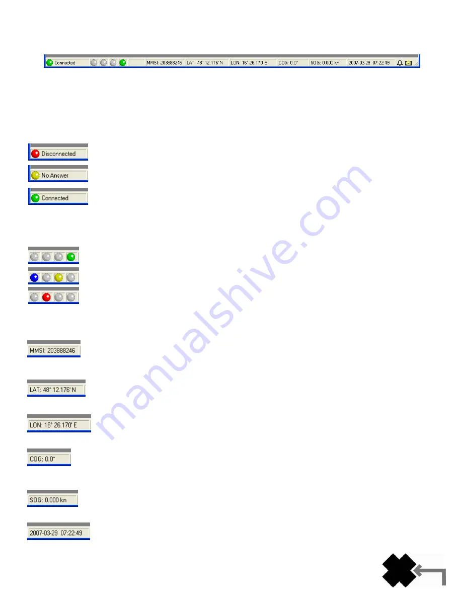
The status bar at the bottom of the main window displays important information of the program and your transponder. 


The fields, from left to right, contain the following information: 

1.  LEDs 

On the left side you‟ll notice icons resembling LEDs. 

Connection Status 

The LEDs on the far left reflect the status of the connection. 


When you start the program you are not connected to the AIS device. 

You have made a connection but the program does not (yet) recognize the device. With amber light: 
some actions (menu items) do not work until the light is green. 

The program and the Nauticast

™-B are communicating properly – connection OK. 


LEDs on your Transponder 

These four LEDs show you which of the LEDs on your Nauticast

™-B are lit. Some possible patterns are: 


 The device is working and OK. 


The “Silent” mode is active – nothing will be sent. 

 An error happened. Read the error message and solve the problem. 

2.  Data Fields 

Most of the status bar is taken by fields that are duplicates of the “Own Ship Data”. 

MMSI 

This is the MMSI (9 digit Marine Mobile Service Identity) of the transponder connected to your PC. 


Latitude 

Your current latitude as computed by your GPS. The longitude and latitude are shown when the GPS 
receiver is able to determine  your position. This is the same position as the one shown in the “Own 
Ship Data

”. 

Longitude 

Your current longitude as computed by your GPS. 


COG 

Your current COG (Course Over Ground) as computed by your GPS.  


SOG 

Your  current  SOG  (Speed  Over  Ground)  as  computed  by  your  GPS.  The  units  can  be  selected  in  the 
program settings dialog. 

Date and Time 

The  UTC  date  and  time  as  transmitted  by  your  GPS  receiver.  Note  that  the  time  may  lag  a  few 
seconds. 


Summary of Contents for AIS LINK2AIS - REV D

Page 1: ......

Page 2: ...rt scenarios may exist whereby the vessel equipped with this AIS transponder is not visible to other AIS transponders CAUTION Before proceeding to install test or use your new ACR Electronics product...

Page 3: ...DOW _________________________________________________ 5 SECTION 4 MENU STRUCTURE _____________________________________________ 5 SECTION 5 STATUS BAR _________________________________________________...

Page 4: ...vailable the program will not be able to communicate with the device The following message appears to warn you about this state NOTE The device requires static data to be entered When connecting to a...

Page 5: ...implify operating this program In the title bar there is the control menu on the far left the title of the program and the state buttons on the far right where the program area can be maximized minimi...

Page 6: ...uare brackets and the orientation mode The zoom factor and the orientation are stored on your PC Each target is identified with the ship s name if it is known When the name is empty or is in the ship...

Page 7: ...ear up to several minutes The radar view shows the targets as viewed from top You can show the radar view as either North Up shortcut Ctrl N or Course Up shortcut Ctrl C The default display mode is No...

Page 8: ...s points up and the north direction is rotated as required Your current Course over Ground is shown by the arrow centered at the top of the screen Ship List This window shows information received from...

Page 9: ...e These settings are stored on your PC All columns can be sorted in ascending or descending order by clicking the column header When opening the ship list window the default sort order is ascending di...

Page 10: ...oks like this Configuring the Transponder For instructions on configuring the transponder please see the Product Support Manual included with this product Own Ship Data This window shows information o...

Page 11: ...still present after several minutes check the GPS antenna position and connection and the clear sky visibility o No check at Pos Report Tx d the AIS has not yet transmitted its position Please allow u...

Page 12: ...in this menu No switch or no action the switch has no function Switch fitted and sends SRM a safety related message MAYDAY MAYDAY is sent once per minute as long as the switch is active Switch fitted...

Page 13: ...th the numbers on the outside representing the standard coordinates of a compass rose The degrees of declination coming from the outer ring coordinates rise from each horizon to 90 being directly over...

Page 14: ...use during installation of the AIS transponder to verify placement and connection of the GPS antenna Each bar represents a satellite with its number noted below the bar AIS Message View A way to moni...

Page 15: ...rom your own Vessel Choose which messages should be displayed The default is VDM received messages only Message number Choose the message number s to be displayed The default is the message 1 only pos...

Page 16: ...16 Y1 03 0223 Rev D AIS Console Log The Console Log is a powerful tool for monitoring AIS traffic As soon as the window opens it starts displaying the information provided by the Nauticast B AIS...

Page 17: ...Toggle display of sent data on off Stop Start Stop or Start if incoming messages are processed by the Console Log This also affects logging to a file Note that this setting is valid only for the curre...

Page 18: ...you need to capture a scenario Capturing the data The data will be stored in a special log file that has to be created This can be done in the log file s menu where you have to ensure that Logfile fo...

Page 19: ...orded from this position If the current situation is of special interest you may pause the Demo Mode at any time with the Pause button To continue playing the button must be pressed again The slider i...

Page 20: ...on has been established between the Nauticast B AIS and the Link2AIS Software a green icon and the text Connected will appear in the bottom left corner of the main screen When the connection is possib...

Page 21: ...nd the message Connected If a connection cannot be made a warning message will appear The icon will remain red and the message will read Disconnected Program Settings This dialog lets you change the d...

Page 22: ...nk to a dialog where you can pick the active window will be shown instead 5 Info Info This provides help and information about the program Help Help is displayed from the accompanying help file of the...

Page 23: ...B are lit Some possible patterns are The device is working and OK The Silent mode is active nothing will be sent An error happened Read the error message and solve the problem 2 Data Fields Most of th...

Page 24: ...nerated by the AIS unit are shown in the alarm window Alarms will be automatically acknowledged when the alarm window is open This can be done by clicking on the bell symbol Note that alarms may take...

Page 25: ...tact your administrator Not connected to network or cable Check if your computer and the Nauticast B have connection to the network IP connection or the same serial cable serial connection Nauticast B...

Page 26: ...ttached card within 10 days Five years for the following products EPIRB PLB S VDR SSAS Useful Life Policy The typical service life of a properly maintained Product is limited to 12 years from date of...

Reviews: