background image


36

8 Channel  DVR

240(200)

120(100)

60(50)

16 Channel DVR

480(400)

240(200)

120(100)


y

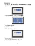
 Click (


) each frame on Quality column to select recording quality of a corresponding camera. You may select one of 

Super, High, and Std

y

  Choose ‘OK’ to confirm the setting.   


y

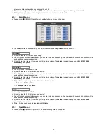
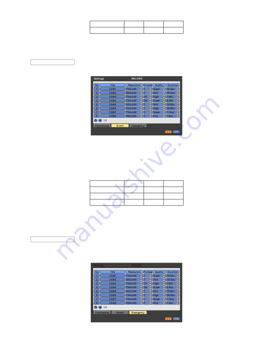
  Please click (


) Event, and the following screen will appear.   


y

  The Event menu will allow you to set Event videos.   

y

  Each frame on Title column shows camera title registered in DEVICES>Camera/PTZ. You cannot change camera titles 

here.  

y

 Click (


) each frame on Resolution column to select recording resolution of a corresponding camera. You may select one of 

704x480, 704x240, and 352x240

y

 Click (


) each frame on Frames column to select recording rate of a corresponding camera. Recording rate varies by 

camera. Below lists the maximum recording rate of each camera. 


NTSC(PAL) 352x240

704x240

704x480

4 Channel  DVR

120(100)

60(50)

30(25)

8 Channel  DVR

240(200)

120(100)

60(50)

16 Channel DVR

480(400)

240(200)

120(100)


y

 Click (


) each frame on Quality column to select recording quality of a corresponding camera. You may select one of 

Super, High, and Std

y

 Click (


) each frame on Duration column to select recording duration (i.e., 

1 second ~3 hours

) of a corresponding camera. 

y

  Choose ‘OK’ to confirm the setting. 


y

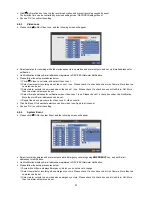
  Please click (


) Emergency, and the following screen will appear Emergency. 

y

  The Emergency menu will allow you to set Emergency videos.   

y

  Each frame on Title column shows camera title registered in DEVICES>Camera/PTZ. You cannot change camera titles 

here.  


Emergency 

Event 

Summary of Contents for Advanced MPEG-4 DVR

Page 1: ...1 Advanced MPEG 4 DVR 4 8 16 Channel Models User s Manual Stand Alone Digital Video Recorder V2 04 2249 This document contains preliminary information and subject to change without notice...

Page 2: ...n and servicing should be performed only by qualified and experienced personnel Power off the DVR when connecting cameras audio or sensor cables The manufacturer is not responsible for any damage caus...

Page 3: ...ous injury to a child or adult and serious damage to the equipment Wall or shelf mounting should follow the manufacturer s instructions and should use a mounting kit approved by the manufacturer Move...

Page 4: ...lation This installation should be made by a qualified service person and should conform to all local codes 17 Correct Batteries 18 Operating Temperature An operating temperature range is specified so...

Page 5: ...4 DVR Set A Type 4CH 8CH 16CH B Type 4CH 8CH 16CH CD Software Manual Remote Controller Manual Screws HDD Brackets Optional THE LIST OF CONFIGURATION...

Page 6: ...ation Status Setup Default HDD format HDD format is done by SETUP SYSTEM Admin Storage Format If there are more than two HDDs each must be formatted separately When the format is completed DVR will au...

Page 7: ...a Mouse 15 3 6 Screen Icons 16 4 Setup 17 4 1 Login Logout 17 4 2 SYSTEM 18 4 2 1 Information 18 4 2 2 Admin 20 4 2 3 Account 24 4 2 4 System Log 26 4 2 5 Exit 26 4 2 6 Shutdown 27 4 3 DISPLAY 27 4 3...

Page 8: ...n Recording Status 63 8 5 5 Alarm In Connection and Operating Status 63 8 5 6 Alarm Out Connection and Operating Status 63 8 6 Remote Setting 63 9 Search Mode 65 9 1 Search Screen 65 9 2 Remote Search...

Page 9: ...ed DVR Main body Power Supply Adapter DC 12V 5A or Power Supply Cable Remote Control With 2 AAA batteries Installation CD CMS Software User s Manual 1 2 Service y If there is any problem in the produc...

Page 10: ...9 B Type 4 8 16 Channel Series DVR...

Page 11: ...Storage SATA 1 2 Port SATA 3 4 Port HDD CD or DVD RW 1 2 3 4 1 1 HDD CD RW DVD RW 2 1 HDD HDD CD RW DVD RW 3 1 HDD HDD HDD CD RW DVD RW B Type 4 8 16 Channel DVR 4 HDD HDD HDD HDD 2 1 2 No Jumper Desi...

Page 12: ...AO 1 AO 4 AO 16 connectors and connect Common to G connector y Connect Pan Tilt receiver or Pan Tilt camera to RS 485 422 connector Please observe proper and polarity 2 2 6 RS 485 422 Connections y P...

Page 13: ...Power Supply Connections y DC powered DVR Plug the power supply adapter included in this product in DC12V connector Input voltage is a free volt 100 VAC 240 VAC Please do not use any different power s...

Page 14: ...Tilt control mode on off MENU Enter the Main Menu Setup mode REW Fast reverse playback changes to x16 x32 with each press Zoom Out in PTZ mode BACKWARD Frame by frame reverse still image playback Zoo...

Page 15: ...press key and use 1 9 key Select Camera No 10 16 press key and use 1 6 key B Type model y Below shows how to select camera channel for 4 8 16channel DVR y Below shows how to select camera channel for...

Page 16: ...n easier access to adjustment Refer to below for proper use y Left mouse button functions the same as Enter key on the front panel of DVR y Right mouse button displays the following Function keys on y...

Page 17: ...recording Event recording mode Alarm In Motion 4 CMS access indication No of accesses up to 4 In recording In channel sequencing PTZ registration PTZ mode Lock Remote Controller Setup in HDD Overwrit...

Page 18: ...approach by the login window See 4 2 3 Account y At Setup System Account menu if you add a user that user s ID will appear and you can login as its general ID y After login successfully following scre...

Page 19: ...Please click direction keys on the right hand side of the System ID frame to set the ID of DVR Take any whole number between 1 and 255 y While pressing or button the System ID value increases or decr...

Page 20: ...ge box will show its success or failure y When you complete Status data input please click Version and the following screen will appear Version Upgrade y You may upgrade DVR software y Please follow t...

Page 21: ...ut The Alarm out will happen at the used amount of HDD which is specified at Used Beep Check 5 the warning sound will happen at the used amount of HDD which is specified at Used Blink Message Check 5...

Page 22: ...live in a region to observe DST please check it i e 5 y If DST is observed please click Period and the following screen will appear y Adjust the dates of beginning Begin and end End of DST by Month We...

Page 23: ...Input IP address of NTP server Interval y Set clock update interval from NTP Server Normally you can adjust 30 min up to 24 hours System Clock y Display DVR clock Server Clock y Display NTP Server s c...

Page 24: ...D damage as the SMART setup y Check 5 Blink Message the alarm message will blink on the OSD as the SMART setup y If you uncheck Used on Beep Blink Message will be unchecked automatically Only when you...

Page 25: ...selectively checking 5 some of the following items Setup Search Network Archiving and Shut Down y Choose OK to confirm the setting y Please click Login Settings and the following screen will appear y...

Page 26: ...y Input Password and Confirm y Choose OK to confirm the setting Then lists of Group and User will show as follows y Click 6 to delete the set Group or User y You may create up to 8 Groups and 8 Users...

Page 27: ...Success Fail Data clear Success Fail USB Upgrade Success Fail DVR Setup Change by Remote Before After Time Adjust y System Log deletion procedure is as follows Execute Clear All Data in SYSTEM Informa...

Page 28: ...just the position of OSD letters on the monitor Use it when some of letters are dropped out and invisible on the monitor y Adjust Horizontal to change margin between both ends of the monitor on horizo...

Page 29: ...Rs y Adjust interval for X4 Split Screen sequencing y Check 5 check box next to the camera you want to include in sequencing Any camera with unchecked check box will be excluded from channel sequencin...

Page 30: ...tor control on display mode y Every click of the SPOT menu item on mouse right click menu will indicate SP and SP1 on the right bottom of main monitor y After SP1 the it shows nothing And system gets...

Page 31: ...each frame y In DHCP IP Address Subnet Mask Gateway and DNS Server will have input automatically DNS Server y When you set Network Type to DHCP DNS server will be inputted automatically y When you set...

Page 32: ...tting y Please click Port and the following screen will appear y Transfer Speed is used for setting a mean transfer speed per unit of time between a client and a DVR y Set a proper Transfer Speed for...

Page 33: ...d will appear Please register IP of SMTP Server mail server on the sender side e g kornet net y Click the keyboard icon on the right hand side of Sender ID frame and the virtual keyboard will appear P...

Page 34: ...r and Pattern help you to use OSD function of PTZ camera PTZ camera itself supports OSD menu use the setup value to more easily enter and use the OSD menu even in DVR If OSD enter command is 95 PSET f...

Page 35: ...t hand side of each frame on Title column and the virtual keyboard will appear Then please register the title of Alarm input y When you check 5 a check box on No column a corresponding Alarm starts op...

Page 36: ...RD and the following screen will appear 4 5 1 Settings y Please click RECORD Settings and the following screen will appear y There are three kinds of recording mode Continuous record continuously Even...

Page 37: ...Frames column to select recording rate of a corresponding camera Recording rate varies by camera Below lists the maximum recording rate of each camera NTSC PAL 352x240 704x240 704x480 4 Channel DVR 1...

Page 38: ...ORD Schedule y Each weekday is composed of 24 Time blocks Each block represent 1 hour y Click Camera frame to select Camera No 1 y Please set the recording mode as follows Check a check box next to yo...

Page 39: ...cording rate of a corresponding camera Recording rate varies by camera Below lists the maximum recording rate of each camera NTSC PAL 352x240 704x240 704x480 4 Channel DVR 120 100 60 50 30 25 8 Channe...

Page 40: ...he setting 4 5 5 Holiday y Please click RECORD Holiday and the following screen will appear y The Holiday menu will allow you to register holidays Please follow the registration procedure below Use ar...

Page 41: ...s on Please check 5 a check box under Link Notification More than two E mail addresses can be set Repeat the above procedure for Alarm In 2 Alarm In 16 y Choose OK to confirm the setting 4 6 2 Motion...

Page 42: ...n two alarm outputs can be set Select E mail addresses for notification when Video Loss 1 is on Please check 5 a check box under Link Notification More than two E mail addresses can be set Repeat the...

Page 43: ...p sound for warning or have a particular channel of interest to pop up on Spot Screen y Please follow the setup procedures below Select camera Popup Please Check 5 a check box under making the popup s...

Page 44: ...disk usage will show by y On the left low side of the screen icon will show as the progress y At the normal state HDD Overwrite mode is on and icon shows y When Overwrite mode is off see 4 2 1 Inform...

Page 45: ...een Please do not use the digital zoom function in split screen format channel sequencing mode or PIP mode 5 1 4 Freeze Live Image y Press FREEZE key while viewing live image to pause the image y The...

Page 46: ...the camera itself you should set them in Camera OSD Once you complete the setup close the Camera OSD menu You can conveniently use Tour and Pattern functions simply by clicking Tour and Pattern button...

Page 47: ...following Search menu will appear y There are three ways to search video i e by date time and by calendar Date Time Search search by inputting date time Calendar Search search by using calendar Event...

Page 48: ...en will show selected date time Click button for selecting cameras Selected camera will show the time bar 0 60 and It will be marked on 2 5minutes basis during selected time zone Use and keys to move...

Page 49: ...en will appear y There are three ways to search video i e by date time and by calendar Date Time Search search by inputting date time Calendar Search search by using calendar Event Search search by ev...

Page 50: ...Goto End I Goto end of recorded data y Press SEARCH key to stop playing back video 5 4 One touch Playback y Press the PLAY PAUSE key or click the mouse wheel central button in the viewing mode Then y...

Page 51: ...Archive Click Start button Then Progress bar will appear and the storage process proceeds If the storage is done properly Archive Success message will pop up Please choose OK to confirm If the storage...

Page 52: ...ust display poison y If you want every camera to have the same mode please click Copy to All Camera y Choose OK to confirm the setting 5 7 Alarm Out Control yPlease click Color Alarm in SEARCH popup m...

Page 53: ...52 CMS Central Monitoring Station User s Manual Stand Alone Digital Video Recorder V2 04 2249 This document contains preliminary information and subject to change without notice...

Page 54: ...SP4 or Windows XP only 6 2 PROGRAM INSTALLATION METHOD y Please follow the program installation procedures below If an old version of CMS program was installed completely remove or delete the old ver...

Page 55: ...s click Install When the following screen appears click Finish to complete the installation 6 3 LOGIN y After you install CMS software CMS icon below appears on your desktop y Please double click on t...

Page 56: ...Setting DVR Setting ARCHIVE Archive Moving Image Playback Image Archive E MAP View E map image DVR Name DVR Activation DVR Select REMOTE CONNECT DVR Connection Network Connection REMOTE DISCONNECT DVR...

Page 57: ...PC and Network setup 8 2 1 System Setup y This menu is for CMS PC setup y CMS VERSION displays current version of CMS y Time Format displays current time and allow user to set date and time y Display...

Page 58: ...dio number among port numbers set in DVR check with SETUP DEVICES Network in your DVR y Remote Site Login Setup input ID and Password Please do not input ID and Password if you want a popup window for...

Page 59: ...ocal Setting again y Site Tree of DVR will show with the video Site Tree lists DVR sites being currently connected to the CMS y This is Live video of the connected DVR y You can connect maxium 4 DVR s...

Page 60: ...d click the button 5 8 quad screen will display Similarly if you select Channel No 16 13 16 quad screen will display y 9 Split Screen Mode Click on 9 SPLIT button and 9 split screen will display The 9...

Page 61: ...camera of Remote Site to any screen Then the camera will display 8 3 4 Screen Color Adjustment y Adjust color of the screen using three bars Brightness Contrast Saturation Selecting a channel and dra...

Page 62: ...en in an area where the DVR is installed 8 3 8 One Touch Recording y Click on INSTANT RECORD button to save video of every channel in HDD of Local System PC with CMS installation 8 4 PTZ Control y Thi...

Page 63: ...s function allows you to check operating status of each unit in DVR connected to CMS y Click on Health Check button in Watch mode and the following screen will appear y The list below describes functi...

Page 64: ...4 y HDD has an error 8 5 3 Recording Status y In recording y Recording is stopped y Above the maximum number of cameras allowed 8 5 4 Motion Recording Status y In motion recording y No motion recordin...

Page 65: ...e and the following SETUP menu same as DVR s will appear on CMS screen y The setup procedure is same as that of DVR y When the setup is completed do not click Exit button on the SETUP screen but click...

Page 66: ...ate Time LED 4 Site Tree DVR and Channels 5 Calendar 6 IMAGE PRINT button 7 IMAGE SAVE button 8 Playback control button 9 Time Select Bar 10 Fast Forward Backward Playback Click to increase the speed...

Page 67: ...ecorded data 5 Time Select Bar y When Date Time search is completed please click Playback control button to begin playback 9 3 LOCAL SEARCH y The LOCAL SEARCH button allows you to playback recorded da...

Page 68: ...Fast Backward Play Fast Forward Play Play Stop I Go to the First Image I Go to the Last Image I Go to the Previous Image I I Go to the Next Image 9 5 2 Print y This is for printing a selected image wi...

Page 69: ...ute Save 9 5 4 Archive y This is to back up the DVR s moving image data to AVI file in PC CMS y Work only in playback mode y Press STOP button first to make sure the playback is stopped and then press...

Page 70: ...69 Designate Archive end time Designate file name Select camera video to save Click on Start button to begin Archive...

Page 71: ...de PAUSE BACKWARD Frame by frame backward still image playback FORWARD Frame by frame forward still image playback REW Fast reverse playback FF I Fast forward playback DEINTERACE Deinterlace On Off 10...

Page 72: ...select remote site tab and the following screen will appear y Please click on file open button and select the E Map file to load y Please click on OK button to exit program y Click button and you can...

Page 73: ...u set up CMS program the application Estimator will set up additionally y The operation screen is as follows y At Setup Record Settings by changing settings you can estimate data size maximum recordin...

Page 74: ...73 Advanced Keyboard Controller User s Manual Keyboard Controller V2 04 2249 This document contains preliminary information and subject to change without notice...

Page 75: ...ss CLR key the operation mode is switched to DVR control mode If you do not input 0 or numbers and presses CLR key only the operation mode is switched to PTZ control mode In DVR control mode a text sa...

Page 76: ...y to change the PIP channel In case of 4 or 9 channel screen it changes the screen to a next one in the sequence FRZ freezes a current image SETUP pops up Setup window PLAY PAUSE plays pauses recorded...

Page 77: ...CTORY SET of the CP main setup and set up the Joystick again MAIN SETUP PASSWORD MAIN SETUP 1 VER MAIN SETUP 2 DATE 20070519 MAIN SETUP 3 TITLE SET MAIN SETUP 4 CONTROL ID 1 MAIN SETUP 5 DVR SPD 9 6k...

Page 78: ...The numbers to be selected are different according to the DVR control mode and PTZ control mode y DVR control mode When KBD SYSTEM ID displays on OSD screen it is DVR control mode The applicable chann...

Page 79: ...78 11 8 System Configuration Diagram 11 8 1 Configuration Diagram I Multi port Rx Rx Trx Tx Tx Max 16 camera Max 16 DVR Multi port Multi port...

Page 80: ...8 2 Configuration Diagram II 11 8 3 Configuration Diagram III Single System Configuration Camera 1 Keyboard 1 DVR 1 Tx Tx Rx Rx DVR PTZ Port Tx1 Tx1 Tx2 Tx2 Tx3 Tx3 Trx RS485 RS485 Trx Tx Tx Max 3 Ca...

Page 81: ...em Configuration connected directly to PTZ Tx Tx Rx Rx DVR PTZ Port Tx1 Tx1 Tx2 Tx2 Tx3 Tx3 Trx RS485 RS485 Trx Tx Tx Rx Rx DVR PTZ Port Tx Tx Tx Tx Tx Tx Trx RS485 RS485 Trx Multi port Tx Tx Rx Rx DV...

Page 82: ...81 Serial In POS ATM User s Manual Serial In POS ATM V2 04 2249 This document contains preliminary information and subject to change without notice...

Page 83: ...nformation from the serial port in real time on the OSD screen Playback displays the saved information on the OSD screen during replay Both displays all the information on both Live and Playback mode...

Page 84: ...um Character Per Line Sets up the number of the minimum strings each line Does not show the characters on OSD screen if there is a character of which number is below the designated number in each line...

Reviews: