15
4 INSTALLATION OF EQUIPMENT
4.1 UNLOADING AND INSPECTION
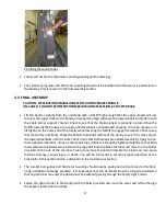
There are restrictions on the lift points of the machine. In order to prevent injury or damage to the machine,
use only the methods shown in this manual. It is important that the machine is lifted directly under the
frame as shown.
Some parts of the Wood Runner have a high center of gravity while being moved and could present a tipping
hazard.
Always use caution when unloading. Keep all personnel clear to prevent injury. Damage to airlines and conduits
must be avoided while unloading. Never install the Gantry onto the Runway before the Runway is bolted down.
The Gantry may tip over causing severe injury or death.
Lift Point on Runway
Lift Point on Gantry
4.2 SITE REQUIREMENTS
PNEUMATIC REQUIREMENTS:
100 PSI (max 120PSI) at 20 SCFM (average). Minimum airline feed
size: ½”diameter
ELECTRICAL REQUIREMENTS
: 208-230 volts 3Phase 50/60Hz 20 amps or 460 volts 3 phase 50/60 Hz
20
amps. Voltage must be specified at time of order.
ENVIRONMENT:
The machine must be installed within a building to provide weather protection.
Intense sunlight, precipitation or windblown dust will cause malfunction and dramatically shorten
the life of the machine. A heated building is required in colder climates. Moisture and condensate
Summary of Contents for Wood Runner
Page 5: ...5 ...
Page 36: ...36 ...
Page 37: ...37 ...
Page 54: ...54 ...
Page 55: ...55 10 DETAILED PARTS IDENTIFICATION WOOD RUNNER 10 1 RUNWAY ASSEMBLY ...
Page 58: ...58 10 3 RUNWAY DRIVE ASSEMBLY ...
Page 61: ...61 10 5 GANTRY ASSEMBLY ...
Page 62: ...62 GANTRY ASSEMBLY ...
Page 64: ...64 10 6 PICKING HEAD ASSEMBLY ...
Page 65: ...65 PICKING HEAD ASSEMBLY ...
Page 68: ...68 10 7 ELECTRICAL PANEL ASSEMBLY ...
Page 70: ...70 10 8 GANTRY ENCLOSURE ASSEMBLY ...
Page 72: ...72 10 9 CONSOLE ASSEMBLY ...
Page 73: ...73 CONSOLE ASSEMBLY ...
Page 75: ...75 10 10 AIR SUPPLY ASSEMBLY ...
Page 77: ...77 10 11 GANTRY VALVE ASSEMBLY ...
Page 79: ...79 10 12 GANTRY BRAKE ASSEMBLY ...
Page 81: ...81 11 ELECTRICAL DIAGRAMS 11 1 SYSTEM OVERVIEW ...
Page 82: ...82 11 2 MAIN ENCLOSURE LOW VOLTAGE ...
Page 83: ...83 11 3 GANTRY WIRING LOW VOLTAGE ...
Page 84: ...84 11 4 I O CHART ...
Page 85: ...85 11 5 INFEED WIRING LOW VOLTAGE ...
Page 86: ...86 11 6 OPERATORS CONSOLE ...
Page 87: ...87 11 7 MAIN ENCLOSURE HIGH VOLTAGE ...
Page 88: ...88 11 8 MAIN ENCLOSURE RECEPTACLE WIRING ...
Page 89: ...89 11 9 SAFETY CIRCUIT LAYOUT ...
Page 90: ...90 11 10 SAFETY CIRCUIT DIAGRAM ...
Page 91: ...91 11 11 BRAKE SENSOR DIAGNOSIS ...
Page 92: ...92 12 PNEUMATIC DIAGRAMS 12 1 SINGLE HEAD GANTRY ...
Page 93: ...93 12 2 DOUBLE HEAD GANTRY ...
Page 94: ...94 12 3 INFEED DECK ...


