


22
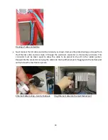
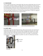
Infeed Deck Power Connection
Connect Ethernet and I/O wire between the Operators console and the Main Electrical Enclosure. Both
ends of the Ethernet cable route through the same type of aluminum connect that was used on the
Gantry. These wires are typically routed through the frame of the Infeed Deck.
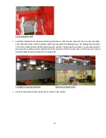
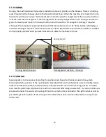
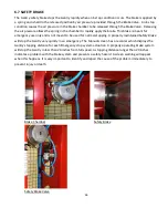
Mount the Light Curtain receiver to its bracket near the saw and mount the emitter to the Forklift Guard.
The receiver has an 8 pin electrical connector; the emitter has a 5 pin connector. The emitter cable is
located in the lower Runway tube and must be fastened along the Perimeter Guard to protect it from
damage. The receiver cable originates from the Operators console. The light curtain will need to be
aligned after the machine is powered up. See the Startup section.
Summary of Contents for Wood Runner
Page 5: ...5 ...
Page 36: ...36 ...
Page 37: ...37 ...
Page 54: ...54 ...
Page 55: ...55 10 DETAILED PARTS IDENTIFICATION WOOD RUNNER 10 1 RUNWAY ASSEMBLY ...
Page 58: ...58 10 3 RUNWAY DRIVE ASSEMBLY ...
Page 61: ...61 10 5 GANTRY ASSEMBLY ...
Page 62: ...62 GANTRY ASSEMBLY ...
Page 64: ...64 10 6 PICKING HEAD ASSEMBLY ...
Page 65: ...65 PICKING HEAD ASSEMBLY ...
Page 68: ...68 10 7 ELECTRICAL PANEL ASSEMBLY ...
Page 70: ...70 10 8 GANTRY ENCLOSURE ASSEMBLY ...
Page 72: ...72 10 9 CONSOLE ASSEMBLY ...
Page 73: ...73 CONSOLE ASSEMBLY ...
Page 75: ...75 10 10 AIR SUPPLY ASSEMBLY ...
Page 77: ...77 10 11 GANTRY VALVE ASSEMBLY ...
Page 79: ...79 10 12 GANTRY BRAKE ASSEMBLY ...
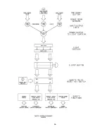
Page 81: ...81 11 ELECTRICAL DIAGRAMS 11 1 SYSTEM OVERVIEW ...
Page 82: ...82 11 2 MAIN ENCLOSURE LOW VOLTAGE ...
Page 83: ...83 11 3 GANTRY WIRING LOW VOLTAGE ...
Page 84: ...84 11 4 I O CHART ...
Page 85: ...85 11 5 INFEED WIRING LOW VOLTAGE ...
Page 86: ...86 11 6 OPERATORS CONSOLE ...
Page 87: ...87 11 7 MAIN ENCLOSURE HIGH VOLTAGE ...
Page 88: ...88 11 8 MAIN ENCLOSURE RECEPTACLE WIRING ...
Page 89: ...89 11 9 SAFETY CIRCUIT LAYOUT ...
Page 90: ...90 11 10 SAFETY CIRCUIT DIAGRAM ...
Page 91: ...91 11 11 BRAKE SENSOR DIAGNOSIS ...
Page 92: ...92 12 PNEUMATIC DIAGRAMS 12 1 SINGLE HEAD GANTRY ...
Page 93: ...93 12 2 DOUBLE HEAD GANTRY ...
Page 94: ...94 12 3 INFEED DECK ...


