


49
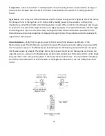
Locknut and Pad Locations
Loosen the locknut on brake chamber
Loosen the locknut on the brake chamber and unscrew the brake chamber by turning it counter-clockwise.
The chamber should unscrew easily if the chamber spring is properly compressed. CAUTION! If it is difficult
to turn, stop and check that the chamber spring has been properly caged.
When reinstalling the chamber screw the chamber clockwise until it bottoms out lightly (the brake pad is
now forced against the Runway rail) and then back it off 1 to 1 1/2 turns (counterclockwise) to provide
running clearance and allow access the storage area for the release tool. Tighten the locknut and reinstall
the airline.
Remove the release tool and replace in in its storage area.
Test the brake function as shown in the Safety section of this manual.
8.11 BRAKE PAD REPLACEMENT
To Replace the Brake Pad Material:
Follow the same steps listed above for caging the brake chamber spring but do not remove the chamber.
Disconnect drive belt from the gantry.
Lift the Gantry vertically off the runway (about 6 inches) until you can remove the brake plunger.
Remove the socket head screw and replace brake pad material.
Reinstall the plunger.
Remove the airline from the Brake Chamber,
Loosen the Brake Chamber locknut an turn the Brake Chamber several turns counterclockwise to provide
more clearance for the new pad.
Lower the Gantry onto the rail.
Rotate the Brake Chamber clockwise until you feel the brake pad contact the Runway. Back it off ½-3/4 turn
for clearance and relock the locknut.
Remove release tool and replace in the storage area.
Locknut
Brake Pad
Material
Summary of Contents for Wood Runner
Page 5: ...5 ...
Page 36: ...36 ...
Page 37: ...37 ...
Page 54: ...54 ...
Page 55: ...55 10 DETAILED PARTS IDENTIFICATION WOOD RUNNER 10 1 RUNWAY ASSEMBLY ...
Page 58: ...58 10 3 RUNWAY DRIVE ASSEMBLY ...
Page 61: ...61 10 5 GANTRY ASSEMBLY ...
Page 62: ...62 GANTRY ASSEMBLY ...
Page 64: ...64 10 6 PICKING HEAD ASSEMBLY ...
Page 65: ...65 PICKING HEAD ASSEMBLY ...
Page 68: ...68 10 7 ELECTRICAL PANEL ASSEMBLY ...
Page 70: ...70 10 8 GANTRY ENCLOSURE ASSEMBLY ...
Page 72: ...72 10 9 CONSOLE ASSEMBLY ...
Page 73: ...73 CONSOLE ASSEMBLY ...
Page 75: ...75 10 10 AIR SUPPLY ASSEMBLY ...
Page 77: ...77 10 11 GANTRY VALVE ASSEMBLY ...
Page 79: ...79 10 12 GANTRY BRAKE ASSEMBLY ...
Page 81: ...81 11 ELECTRICAL DIAGRAMS 11 1 SYSTEM OVERVIEW ...
Page 82: ...82 11 2 MAIN ENCLOSURE LOW VOLTAGE ...
Page 83: ...83 11 3 GANTRY WIRING LOW VOLTAGE ...
Page 84: ...84 11 4 I O CHART ...
Page 85: ...85 11 5 INFEED WIRING LOW VOLTAGE ...
Page 86: ...86 11 6 OPERATORS CONSOLE ...
Page 87: ...87 11 7 MAIN ENCLOSURE HIGH VOLTAGE ...
Page 88: ...88 11 8 MAIN ENCLOSURE RECEPTACLE WIRING ...
Page 89: ...89 11 9 SAFETY CIRCUIT LAYOUT ...
Page 90: ...90 11 10 SAFETY CIRCUIT DIAGRAM ...
Page 91: ...91 11 11 BRAKE SENSOR DIAGNOSIS ...
Page 92: ...92 12 PNEUMATIC DIAGRAMS 12 1 SINGLE HEAD GANTRY ...
Page 93: ...93 12 2 DOUBLE HEAD GANTRY ...
Page 94: ...94 12 3 INFEED DECK ...


