31
6 SAFETY SYSTEM DESCRIPTION AND TROUBLESHOOTING
The Wood Runner system is equipped with several safety components to insure the safety of the operator
and other personnel. These components make up the Safety system and work together to shut down the
Wood Runner system when a dangerous condition exists.
NEVER
modify, tamper with or remove any part of this safety system as severe injury or death may occur.
Test the function daily before operating the machine. Do not operate the machine if any part of the safety
system is not functioning correctly. Have the safety system repaired and tested before placing it back in
service.
Components of the Safety system are:
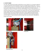
6.1 LIGHT CURTAIN
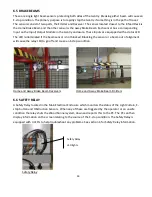
A special safety sensor containing multiple beams of invisible light which cause an E-stop to be triggered
when the beams are broken by a person or object. The Light Curtain is made up of two parts, the
Transmitter and the Receiver. The Transmitter sends out the light beams and the Receiver receives them.
Any interruption in one of the beams will trigger the Receiver. The Light Curtain detects when a person
enters the Hazardous Zone through the open side of the Perimeter Guarding and shuts the system down.
Light Curtain Receiver
Light Curtain Transmitter
Summary of Contents for Wood Runner
Page 5: ...5 ...
Page 36: ...36 ...
Page 37: ...37 ...
Page 54: ...54 ...
Page 55: ...55 10 DETAILED PARTS IDENTIFICATION WOOD RUNNER 10 1 RUNWAY ASSEMBLY ...
Page 58: ...58 10 3 RUNWAY DRIVE ASSEMBLY ...
Page 61: ...61 10 5 GANTRY ASSEMBLY ...
Page 62: ...62 GANTRY ASSEMBLY ...
Page 64: ...64 10 6 PICKING HEAD ASSEMBLY ...
Page 65: ...65 PICKING HEAD ASSEMBLY ...
Page 68: ...68 10 7 ELECTRICAL PANEL ASSEMBLY ...
Page 70: ...70 10 8 GANTRY ENCLOSURE ASSEMBLY ...
Page 72: ...72 10 9 CONSOLE ASSEMBLY ...
Page 73: ...73 CONSOLE ASSEMBLY ...
Page 75: ...75 10 10 AIR SUPPLY ASSEMBLY ...
Page 77: ...77 10 11 GANTRY VALVE ASSEMBLY ...
Page 79: ...79 10 12 GANTRY BRAKE ASSEMBLY ...
Page 81: ...81 11 ELECTRICAL DIAGRAMS 11 1 SYSTEM OVERVIEW ...
Page 82: ...82 11 2 MAIN ENCLOSURE LOW VOLTAGE ...
Page 83: ...83 11 3 GANTRY WIRING LOW VOLTAGE ...
Page 84: ...84 11 4 I O CHART ...
Page 85: ...85 11 5 INFEED WIRING LOW VOLTAGE ...
Page 86: ...86 11 6 OPERATORS CONSOLE ...
Page 87: ...87 11 7 MAIN ENCLOSURE HIGH VOLTAGE ...
Page 88: ...88 11 8 MAIN ENCLOSURE RECEPTACLE WIRING ...
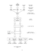
Page 89: ...89 11 9 SAFETY CIRCUIT LAYOUT ...
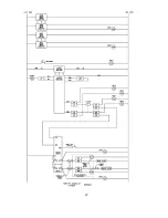
Page 90: ...90 11 10 SAFETY CIRCUIT DIAGRAM ...
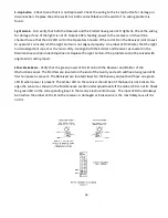
Page 91: ...91 11 11 BRAKE SENSOR DIAGNOSIS ...
Page 92: ...92 12 PNEUMATIC DIAGRAMS 12 1 SINGLE HEAD GANTRY ...
Page 93: ...93 12 2 DOUBLE HEAD GANTRY ...
Page 94: ...94 12 3 INFEED DECK ...

