


88
Chapter 3: Replacing notebook components
4
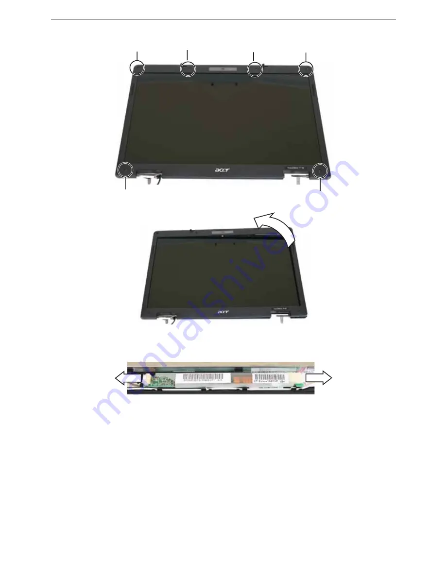
Remove the screws from the front of the LCD panel assembly.
5
Carefully separate the front and back of the LCD panel assembly.
6
Lift the inverter from the LCD panel assembly.
7
Disconnect the connectors from the old inverter and connect them to the new
inverter.
8
Align the holes in new inverter with the pegs in the LCD lid, then press the inverter
into place.
9
Press the LCD panel front and back together. Press the two halves together in
several places until they click in place. You should find no loose spots or spots
where the two halves do not meet.
10
Replace the LCD panel assembly screws removed in
Step 4
.
11
Replace the rubber inserts removed in
Step 3
.
12
Replace the LCD panel by following the steps in
“Replacing the LCD assembly” on
page 84
.
Screw
Screw
Screw
Screw
Screw
Screw
Summary of Contents for TRAVELMATE 7730
Page 1: ...TravelMate 7730 7730A Service Guide ...
Page 4: ...IV ...
Page 8: ...VIII Contents ...
Page 13: ...Chapter 1 System specifications 5 System block diagram ...
Page 42: ...34 Chapter 1 System specifications ...
Page 58: ...50 Chapter 2 System utilities ...
Page 67: ...Chapter 3 Replacing notebook components 59 5 Pull the memory module out of the slot ...
Page 104: ......
Page 105: ......
Page 144: ...134 Chapter 3 Replacing notebook components ...
Page 164: ...154 Chapter 4 Troubleshooting ...
Page 170: ...160 Chapter 5 Jumper and connector locations ...
Page 183: ...173 Model definition and configuration Appendix A TravelMate 7730 7730G ...
Page 248: ...238 Appendix B Test compatible components ...
Page 250: ...240 Appendix C Online support information ...
Page 253: ......
Page 254: ...MAN MONSERRAT SVC GDE R0 06 08 ...