


84
Chapter 3: Replacing notebook components
Replacing the LCD assembly
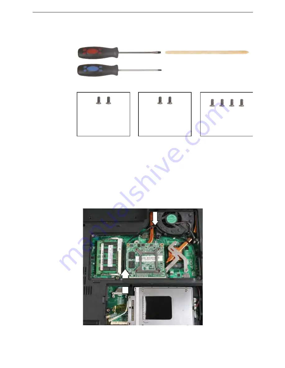
Tools you need to complete this task:
v
Screws removed during this task:
To replace the LCD assembly:
1
Complete the steps in
“Preparing the notebook” on page 55
.
2
Open the memory bay by following the steps in
“Adding or replacing memory
modules” on page 57
.
3
Open the wireless bay by following the steps in
“Replacing the IEEE 802.11 wireless
card” on page 67
.
4
If the notebook has wireless networking built in, unplug the wireless antennas by
following the steps in
“Replacing the IEEE 802.11 wireless card” on page 67
.
5
Taking care to note the cables’ routing and positions as they are installed from
Acer, slide the antenna cables out of the wireless bay.
Flat-blade driver
Scribe or non-marring
- OR -
Phillips #0 screwdriver
4 black M2.5×6.5
(Hinge-top)
2 black M2.5×6.5
(Hinge-bottom)
2 black M2.5×5
(Keyboard cover)
Summary of Contents for TRAVELMATE 7730
Page 1: ...TravelMate 7730 7730A Service Guide ...
Page 4: ...IV ...
Page 8: ...VIII Contents ...
Page 13: ...Chapter 1 System specifications 5 System block diagram ...
Page 42: ...34 Chapter 1 System specifications ...
Page 58: ...50 Chapter 2 System utilities ...
Page 67: ...Chapter 3 Replacing notebook components 59 5 Pull the memory module out of the slot ...
Page 104: ......
Page 105: ......
Page 144: ...134 Chapter 3 Replacing notebook components ...
Page 164: ...154 Chapter 4 Troubleshooting ...
Page 170: ...160 Chapter 5 Jumper and connector locations ...
Page 183: ...173 Model definition and configuration Appendix A TravelMate 7730 7730G ...
Page 248: ...238 Appendix B Test compatible components ...
Page 250: ...240 Appendix C Online support information ...
Page 253: ......
Page 254: ...MAN MONSERRAT SVC GDE R0 06 08 ...