


Chapter 3: Replacing notebook components
99
12
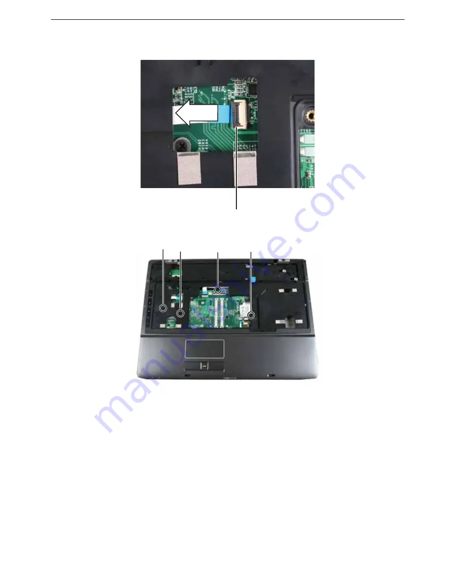
Swing the black button board connector clip upward, then lift the button board
cable out of the connector. Be careful not to touch or damage any other
components.
13
Remove the screws from the top of the palm rest.
14
Turn the notebook over so the bottom is facing up.
Button board
connector
Screw
Screw
Screw Screw
Summary of Contents for TRAVELMATE 7730
Page 1: ...TravelMate 7730 7730A Service Guide ...
Page 4: ...IV ...
Page 8: ...VIII Contents ...
Page 13: ...Chapter 1 System specifications 5 System block diagram ...
Page 42: ...34 Chapter 1 System specifications ...
Page 58: ...50 Chapter 2 System utilities ...
Page 67: ...Chapter 3 Replacing notebook components 59 5 Pull the memory module out of the slot ...
Page 104: ......
Page 105: ......
Page 144: ...134 Chapter 3 Replacing notebook components ...
Page 164: ...154 Chapter 4 Troubleshooting ...
Page 170: ...160 Chapter 5 Jumper and connector locations ...
Page 183: ...173 Model definition and configuration Appendix A TravelMate 7730 7730G ...
Page 248: ...238 Appendix B Test compatible components ...
Page 250: ...240 Appendix C Online support information ...
Page 253: ......
Page 254: ...MAN MONSERRAT SVC GDE R0 06 08 ...