


Chapter 3: Replacing notebook components
127
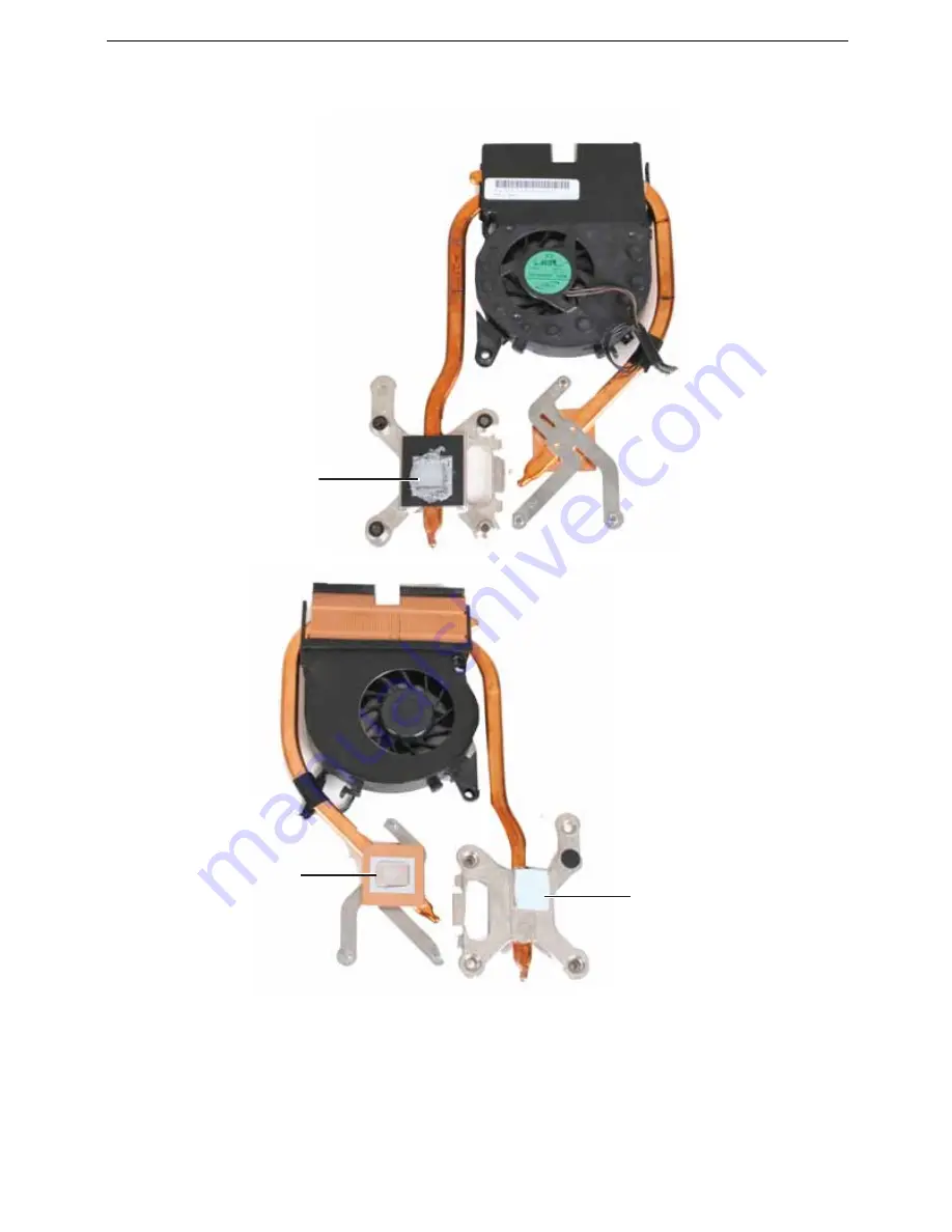
18
Make sure a thermal pad is placed between the new cooling assembly and other
components as shown.
19
Insert the new cooling assembly into the notebook.
20
Tighten the captive screws that secure the cooling assembly to the system board.
Use the numbers stamped in the metal next to each screw and tighten the screws in
numerical order (start with 1, then 2, then 3).
Caution:
When tightening the cooling assembly’s screws into the
numbered holes, tighten them in numerical order.
21
Replace the other cooling assembly screws removed in
Step 14
.
Thermal
grease
Thermal
grease
Thermal pad
Summary of Contents for TRAVELMATE 7730
Page 1: ...TravelMate 7730 7730A Service Guide ...
Page 4: ...IV ...
Page 8: ...VIII Contents ...
Page 13: ...Chapter 1 System specifications 5 System block diagram ...
Page 42: ...34 Chapter 1 System specifications ...
Page 58: ...50 Chapter 2 System utilities ...
Page 67: ...Chapter 3 Replacing notebook components 59 5 Pull the memory module out of the slot ...
Page 104: ......
Page 105: ......
Page 144: ...134 Chapter 3 Replacing notebook components ...
Page 164: ...154 Chapter 4 Troubleshooting ...
Page 170: ...160 Chapter 5 Jumper and connector locations ...
Page 183: ...173 Model definition and configuration Appendix A TravelMate 7730 7730G ...
Page 248: ...238 Appendix B Test compatible components ...
Page 250: ...240 Appendix C Online support information ...
Page 253: ......
Page 254: ...MAN MONSERRAT SVC GDE R0 06 08 ...