


Chapter 3: Replacing notebook components
85
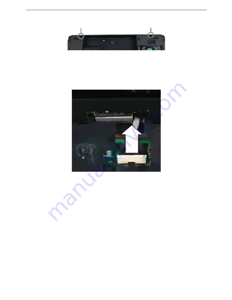
6
Remove the screws on the bottom that secure the LCD panel hinges to the chassis.
7
Remove the keyboard cover by following the steps in
“Replacing the keyboard
cover” on page 78
.
8
Remove the keyboard by following the steps in
“Replacing the keyboard” on page
80
.
9
Detach the LCD cable from the system board. Use a scribe or other non-marring tool
to gently push the plug out of the connector.
Caution:
The LCD video cable connector is fragile.
Screw
Screw
Summary of Contents for TRAVELMATE 7730
Page 1: ...TravelMate 7730 7730A Service Guide ...
Page 4: ...IV ...
Page 8: ...VIII Contents ...
Page 13: ...Chapter 1 System specifications 5 System block diagram ...
Page 42: ...34 Chapter 1 System specifications ...
Page 58: ...50 Chapter 2 System utilities ...
Page 67: ...Chapter 3 Replacing notebook components 59 5 Pull the memory module out of the slot ...
Page 104: ......
Page 105: ......
Page 144: ...134 Chapter 3 Replacing notebook components ...
Page 164: ...154 Chapter 4 Troubleshooting ...
Page 170: ...160 Chapter 5 Jumper and connector locations ...
Page 183: ...173 Model definition and configuration Appendix A TravelMate 7730 7730G ...
Page 248: ...238 Appendix B Test compatible components ...
Page 250: ...240 Appendix C Online support information ...
Page 253: ......
Page 254: ...MAN MONSERRAT SVC GDE R0 06 08 ...