


Chapter 3: Replacing notebook components
107
4
Remove the hard drive(s) by following the steps in
“Replacing the primary hard
drive” on page 64
and
“Replacing the secondary hard drive” on page 73
.
5
Remove the keyboard cover by following the steps in
“Replacing the keyboard
cover” on page 78
.
6
Remove the keyboard by following the steps in
“Replacing the keyboard” on page
80
.
7
Remove the LCD assembly by following the steps in
“Replacing the LCD assembly”
on page 84
.
8
Remove the palm rest by following the instructions in
“Replacing the palm rest” on
page 96
.
9
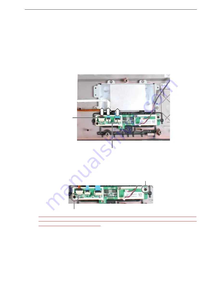
Swing the black touchpad connector clip upward, then lift the touchpad cables out
of the connectors. Be careful not to touch or damage any other components.
10
Disconnect the finger print reader cable from the assembly. Use a scribe or other
non-marring tool to gently push the plug out of the connector.
11
Remove the screws securing the touchpad button board/fingerprint assembly to the
palm rest, then lift the assembly out of the notebook.
<Athena: Does the green square touchpad board get replaced in this procedure, another
procedure, or not at all? I do not see it on the Replacement Parts List and I do not see the
bracket screws in the Screw Specs.>
12
Replace the touchpad button board/fingerprint assembly, then replace the screws
removed in
Step 5
.
13
Make sure the black touchpad connector clip is swung upward, insert the cable into
the connector, then swing the clip down to lock the connector in place.
Important:
The cable is correctly oriented if it is not twisted and the blue
band is facing up.
14
Connect the finger print reader cable to the touchpad button board/fingerprint
assembly.
Touchpad cable
connectors
Fingerprint
reader cable
connector
Screw
Screw
Summary of Contents for TRAVELMATE 7730
Page 1: ...TravelMate 7730 7730A Service Guide ...
Page 4: ...IV ...
Page 8: ...VIII Contents ...
Page 13: ...Chapter 1 System specifications 5 System block diagram ...
Page 42: ...34 Chapter 1 System specifications ...
Page 58: ...50 Chapter 2 System utilities ...
Page 67: ...Chapter 3 Replacing notebook components 59 5 Pull the memory module out of the slot ...
Page 104: ......
Page 105: ......
Page 144: ...134 Chapter 3 Replacing notebook components ...
Page 164: ...154 Chapter 4 Troubleshooting ...
Page 170: ...160 Chapter 5 Jumper and connector locations ...
Page 183: ...173 Model definition and configuration Appendix A TravelMate 7730 7730G ...
Page 248: ...238 Appendix B Test compatible components ...
Page 250: ...240 Appendix C Online support information ...
Page 253: ......
Page 254: ...MAN MONSERRAT SVC GDE R0 06 08 ...