80
Chapter 12
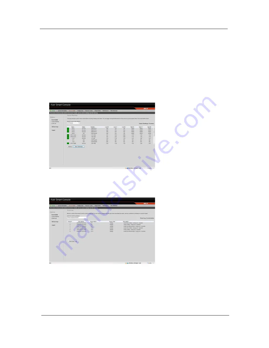
Sensor Display Color
Indicates the health of the system processor, fan, temperature and voltage in a box displayed before each
sensor category.
•
Green
: Indicates the system is in good health and no alerts were detected on the sensors.
•
Amber
: Indicates at least one sensor has a warning alert.
•
Red
: Indicates at least on sensor has a critical alert.
Threshold
Click
Show Thresholds
to view the threshold parameters of each sensor. It displays the Low Non-Critical
(NC), High Non-Critical (NC), High Critical Threshold (CT) threshold information, and these items can not be
modified. When each threshold matches alert level, system will send the alert to the specified destinations. To
configure the specified destination, please go to Alert section. To refresh the sensor status, just click
Refresh
.
Event Log
Provides a record of system events related to critical hardware components. It logs the events when the
sensor triggers an abnormal state or is recovering from an abnormal state. When the log matches a pre-
defined alert, the system will send out a notification automatically if pre-configured.
Configuration
Allows you to designate email recipients for notification of system alerts, configure the Date and Time,
configure the LDAP (Lightweight Directory Access Protocol) and RADIUS settings, configure the mouse mode
Summary of Contents for AW2000h-AW175h F1
Page 1: ...Acer AW2000h Service Guide PART NO PRINTED IN TAIWAN ...
Page 8: ...2 Chapter 1 System parts list Currently unavailable ...
Page 14: ...8 Chapter 2 ...
Page 26: ...20 Chapter 4 ...
Page 32: ...26 Chapter 5 ...
Page 41: ...Hardware removal and installation 35 c Lock the HDD carrier ...
Page 85: ...Chapter 10 79 ...
Page 86: ...80 Chapter 10 ...
Page 87: ...Chapter 11 81 Information unavailable BIOS POST Error Messages List Chapter 11 ...
Page 88: ...82 Chapter 11 ...


