Chapter 12
79
Acer Smart Console user interface
The Acer Smart Console page opens once you have logged in. This page provides a central location for
managing all connected servers. The user interface includes a system status alert indicator, function list, menu
bar, function title, section information.
System status
The system status indicator, located in the upper left-hand corner of the Acer Smart Console page, monitors
and displays the system health and stability. The system sensors allow you to monitor the system's hardware
parameters, such as fan performance, temperature sensors, voltages, and power status. The following are the
different system health statuses that may be displayed on the console.
•
Normal
: The system is in good health and no alerts were detected on the sensors.
•
Warning
: At least one sensor has a warning alert.
•
Critical
: At least one sensor has a critical alert.
System Information
The System Information menu includes options that allow you to view general system information and the
system FRU (field replaceable units). Selecting the System Information menu displays the system information
and FRU readings options in the left pane.
System Information
Displays general server information, such as the power status, management network IP and management
controller MAC address, BMC firmware version and build time, FRU revision and SDR revision and allows you
to manage the chassis LED indicator.
FRU Reading
Provides information about major system components, including chassis, main board and other product
information.
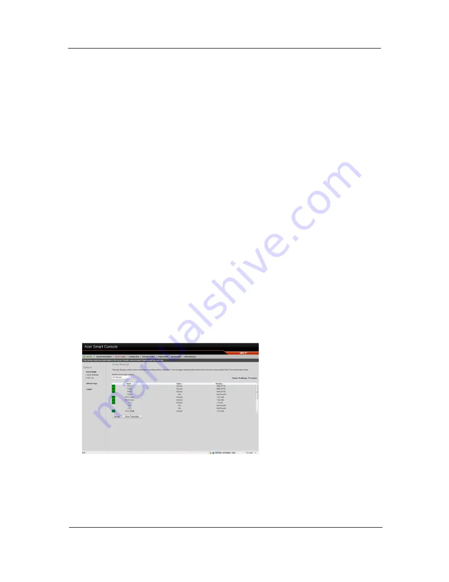
Server Health
Displays data related to the server's health, such as sensor readings and the event log. This menu has two
options: Sensor Readings and Event Log.
Sensor Readings
Allows you to monitor status of the voltages of the power supply, the fan speed, processor and system
temperature sensors.
Summary of Contents for AW2000h-AW175h F1
Page 1: ...Acer AW2000h Service Guide PART NO PRINTED IN TAIWAN ...
Page 8: ...2 Chapter 1 System parts list Currently unavailable ...
Page 14: ...8 Chapter 2 ...
Page 26: ...20 Chapter 4 ...
Page 32: ...26 Chapter 5 ...
Page 41: ...Hardware removal and installation 35 c Lock the HDD carrier ...
Page 85: ...Chapter 10 79 ...
Page 86: ...80 Chapter 10 ...
Page 87: ...Chapter 11 81 Information unavailable BIOS POST Error Messages List Chapter 11 ...
Page 88: ...82 Chapter 11 ...


