Chapter 4
17
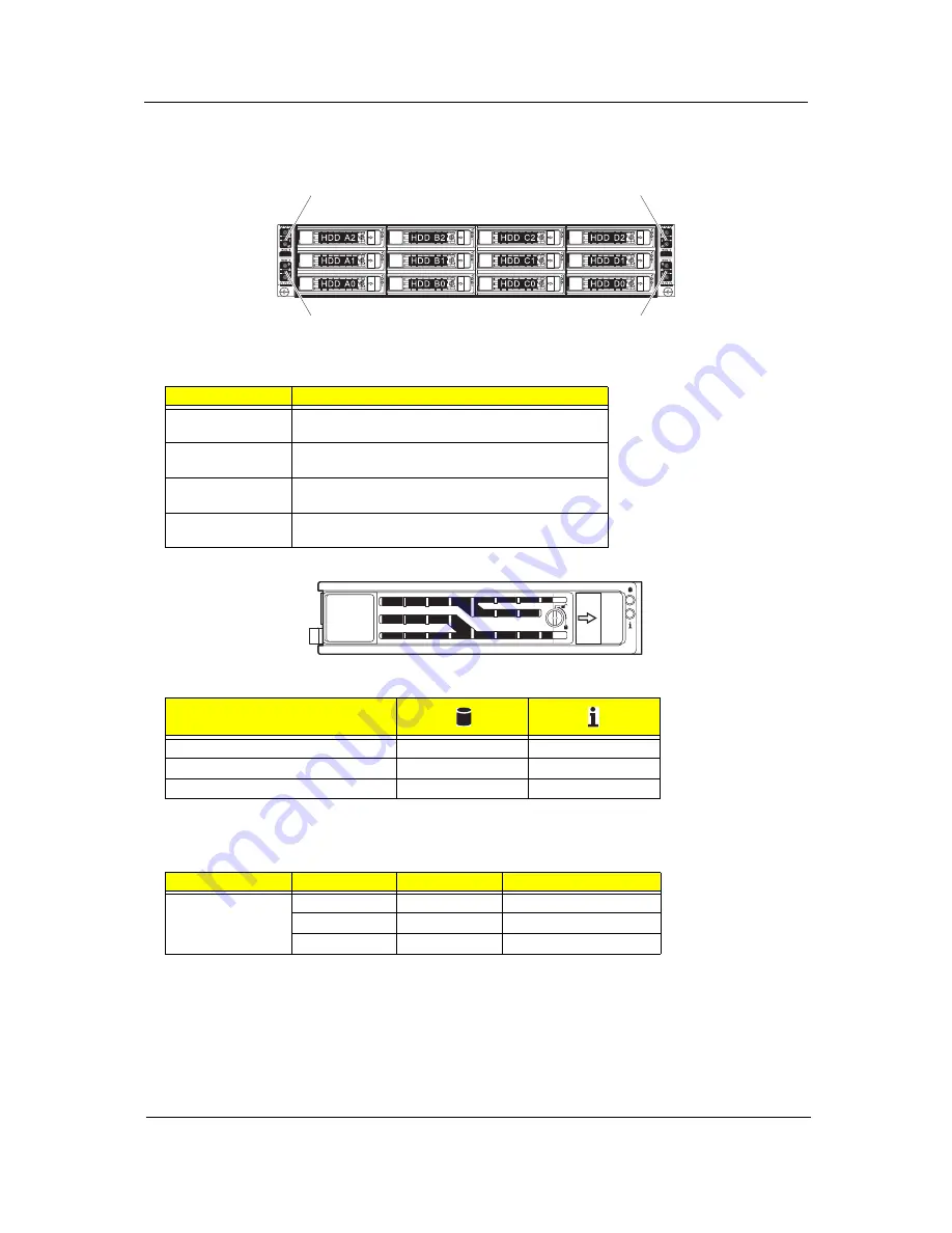
Hard disk drive sequence and LED indicators
The hard drive sequence is as follows:
Drive activity LED indicators are mounted on the hot-plug HDD carrier.
The table below lists the possible drive states.
Rear panel LED indicators
Bay no.
Description
Node A
HDD A0 to A2
Three 3.5-inch hot-plug drive bays controlled by node A
Node B
HDD B0 to B2
Three 3.5-inch hot-plug drive bays controlled by node B
Node C
HDD C0 to C2
Three 3.5-inch hot-plug drive bays controlled by node C
Node D
HDD D0 to D2
Three 3.5-inch hot-plug drive bays controlled by node D
Description
Blue
Red
HDD present no access
Off
Off
HDD access
Blink
Off
LED indicator
LED color
LED state
Status
System ID indicator
N/A
Off
Normal
Blue
On
System identification
Blue
Blinking
IPMI-activated system ID
Node B control panel
Node D control panel
Node A control panel
Node C control panel
Drive bays for
node A
Drive bays for
node B
Drive bays for
node C
Drive bays for
node D
Summary of Contents for AW2000h-AW175h F1
Page 1: ...Acer AW2000h Service Guide PART NO PRINTED IN TAIWAN ...
Page 8: ...2 Chapter 1 System parts list Currently unavailable ...
Page 14: ...8 Chapter 2 ...
Page 26: ...20 Chapter 4 ...
Page 32: ...26 Chapter 5 ...
Page 41: ...Hardware removal and installation 35 c Lock the HDD carrier ...
Page 85: ...Chapter 10 79 ...
Page 86: ...80 Chapter 10 ...
Page 87: ...Chapter 11 81 Information unavailable BIOS POST Error Messages List Chapter 11 ...
Page 88: ...82 Chapter 11 ...


