


Jumper and Connector Locations
5-7
3.
Change name of desired BIOS ROM file to
AMIBOOT.rom
.
4.
Copy
AMIBOOT.rom
file to USB HDD.
5.
Press Power button.
6.
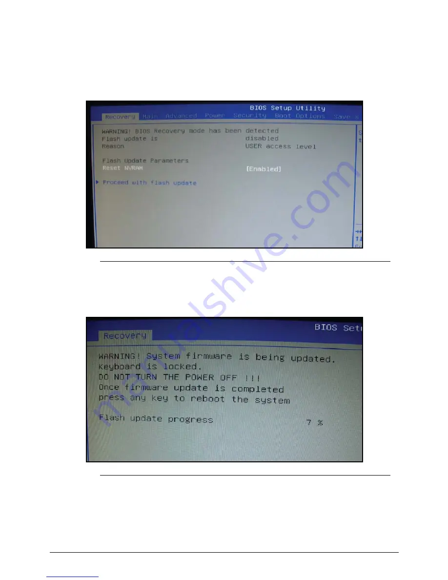
After several minutes, BIOS Setup Utility screen will appear as shown in Figure 5-4.
Figure 5-4.
BIOS Recovery Screen
7.
Select Proceed with flash update.
8.
Press Enter button to initiate BIOS Recovery mode. Flash will begin. (Figure 5-5)
Figure 5-5.
Flash Update Progress
9.
When BIOS Recovery is complete, press F10 to save and exit.
10. Press Del to return to BIOS setup menu.
Update the latest BIOS version for this machine by the regular BIOS flashing process.
Summary of Contents for Aspire Z3801
Page 1: ...i Aspire Z3801 SERVICE GUIDE ...
Page 10: ...x ...
Page 11: ...CHAPTER 1 Hardware Specifications ...
Page 14: ...1 4 ...
Page 45: ...CHAPTER 2 System Utilities ...
Page 71: ...CHAPTER 3 Machine Maintenance Procedures ...
Page 74: ...3 4 ...
Page 120: ...3 50 Machine Maintenance Procedures ...
Page 121: ...CHAPTER 4 Troubleshooting ...
Page 143: ...CHAPTER 5 Jumper and Connector Locations ...
Page 150: ...5 8 Jumper and Connector Locations ...
Page 151: ...CHAPTER 6 FRU Field Replaceable Unit List ...
Page 152: ...6 2 Exploded Diagram 6 4 Main Assembly 6 4 FRU List 6 6 Screw List 6 7 ...
Page 173: ...CHAPTER 7 Online Support Information ...
Page 174: ...7 2 Support Service 7 3 ...
Page 176: ...7 4 Online Support Information ...


