


1 System tour
24
System LED indicators
This section discusses the different LED indicators located on the:
•
Front panel
•
Hot-plug HDD carrier
•
LAN port
Knowing what each LED indicator signifies can aid in problem
diagnosis and troubleshooting.
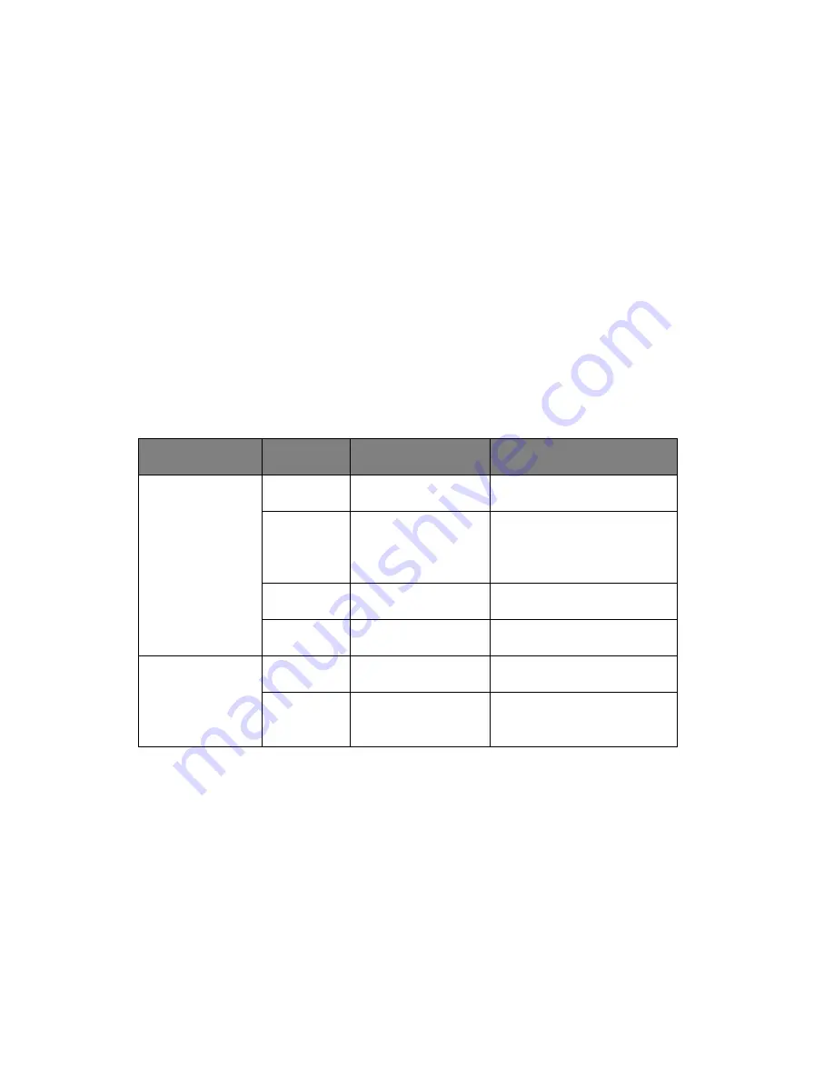
Front panel LED indicators
The six LED indicators mounted on the front bezel. These indicators
remain visible even when the bezel door is closed.
Indicator
Color
State
Representative Status
Power
Green
ON
S0: Power ON
Green
Blink (1Hz with
at 50% duty
cycle)
S1: Sleep
N/A
OFF
S4
N/A
OFF
S5
HDD activity
Green
Blink
HDD Access
N/A
OFF
No access and No HDD
fault
Summary of Contents for Altos G540 M2 Series
Page 1: ...Acer Altos G540 M2 Series User s Guide ...
Page 10: ...x ...
Page 11: ...1 System tour ...
Page 30: ...1 System tour 20 60 CPU2 Processor 2 Socket No Code Description ...
Page 38: ...1 System tour 28 ...
Page 39: ...2 System setup ...
Page 49: ...3 System upgrade ...
Page 69: ...59 2 Detach the plastic frame from the HDD carrier ...
Page 77: ...67 2 Connect the power and SATA cables to the new 5 25 inch drive ...
Page 105: ...4 System BIOS ...
Page 112: ...4 System BIOS 104 Processor Configuration ...
Page 122: ...4 System BIOS 114 Intel VT for Directed I O VT d ...
Page 143: ...5 System troubleshooting ...
Page 154: ...5 System troubleshooting 146 ...
Page 155: ...Appendix A Server management tools ...
Page 165: ...Appendix B Rack mount configuration ...
Page 166: ...This appendix shows you how to set up the Altos G540 M2 server in a rack mount configuration ...
Page 174: ...Appendix B Rack mount configuration 166 6 Fully extend the mounting rails on the rack ...
Page 177: ...169 7 Route all cables through the cable clips ...
Page 178: ...Appendix B Rack mount configuration 170 ...
Page 179: ...Appendix C Altos eXpress Console ...
Page 180: ...This appendix familiarize you to a standard web browser with a nice graphical user interface ...


