background image

41

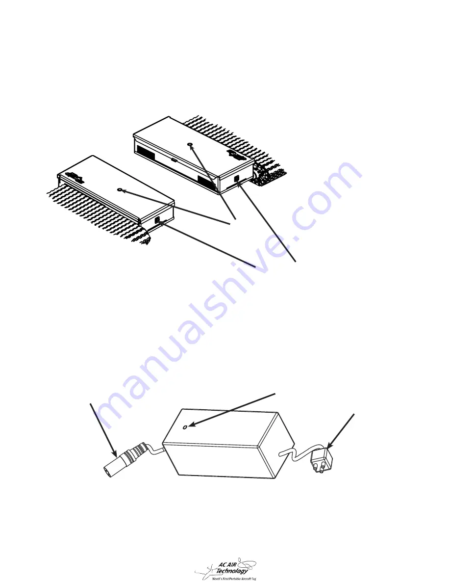
5-2. Charging the Tug

1. Before charging your tug, the radio and tug should both be turned OFF.

2.  Plug charger into charging jack and into a wall socket. The plug can only be
 

     inserted in one direction.

3. Normal charger indicator lights:  


Red…………………Charging


Solid Green…………Fully Charged


Flashing Green………No Longer Charging

4.  Leave the charger connected to the tug whenever the tug is not being used. The 

charger is a “smart” charger and this will prolong the life of the battery. 

110 V Power 

Connection

Tug Connection

Charging Indicator 

LED

Power Switch

Tug Charging Jacks

Summary of Contents for T1H3

Page 1: ...Instruction Manual MODEL T1H3 Helicopter Tug World s First Portable Remote Control Aircraft Tugs 95679 Rev A...

Page 2: ...xiliary Wheels and Lifter Pole 15 3 Tug Assembly 16 3 1 Front End Assembly 16 3 2 Back End Assembly 22 4 Tug Operation 27 4 1 Radio Operation 27 4 2 Operating the Tug 28 4 3 Adjusting the Width of the...

Page 3: ...3 1 Components 1 1 Components in the Box 1 Right Main Tug Assm 05153 Left Main Tug Assm 05153...

Page 4: ...4 1 2 Components in the Box 2 Left End Assembly Assm 09889 Right End Assembly Assm 09993 Short Front end Adjuster Assm 09621 Long Back end Adjuster Assm 09622 2X Frame Side Support Part 02617...

Page 5: ...5 1 3 Components in the Box 3 Auxiliary Wheels Assm 02532 Lifter Pole Assm 02533 Air Bag Part 95623 Hand Pump and Hose Assm 02532...

Page 6: ...art 02629 Battery Tray Part 95087 Radio Charger Part 95102 2X Tug Charger Part 95394 Owners Manual Part 95679 2X Spare Parts Bag Part 09551 4X T Handle Part 95545 4X T1H3 Frame Insert Part 24244 12X S...

Page 7: ...1 Track Assembly Main Plate Skid Loading Rollers Skid Guide Rollers Tug Charger Connection Power Switch Right Back end Connection Slot Side to Side Swivel Connection Note Left Main Tug is an Identica...

Page 8: ...ection Right Main Tug Swivel Connection 1 6 Tug Components 2 Left Back End Insert Right Back End Insert Left Back End Insert Hole Right Back End Side to Side Insert Right Back End Connection Slot Righ...

Page 9: ...the power switch is turned OFF Note If the remote is not used for more than a couple minutes it will start beeping as a indicator that it is still in the ON position This is not an indicator of a low...

Page 10: ...10 1 8 Charger Components Tug Charger 2 Included Radio Charger 110 V Power Connection Tug Connection Charging Indicator LED 110 V Power Connection Radio Connection...

Page 11: ...1 9 Spare Parts Kit 4 4 Spare Track Parts Pins Rotoclips Treads Links Retainer Clip Tool Track Pin Tools 4 Amp Replacement Light Fuse 4 Amp Replacement Light Fuse Track Install Tools Spare Track Part...

Page 12: ...the groove Retainer Clip Tool Rotoclip Teeth Pointing Down Track Pin The Track Tools are used to assist in the installation of new tracks This section is intended to show how the tools are used only A...

Page 13: ...rack Pin Tools are used to assist in the installation of new tracks Insert the Track Pin Tools on the inside and outside adjacent pins to the missing pin hole Note You will need to hold these in place...

Page 14: ...In ate the Air Bag to 50 60 capacity Place the Air Bag centered underneath the tail of the helicopter as shown As the tug approaches the helicopter s center of gravity the tail will pivot down and res...

Page 15: ...f the track On the opposite end of the track po sition the Lifer Pole underneath the main plate Install the second auxiliary wheel Lifer Pole Auxiliary Wheels If one track loses power the auxiliary wh...

Page 16: ...e 1 2 4 3 Center Numbered Tube Insert End Numbered Tube Insert 5 Center Tube 6 Adj Handle NOTE BEFORE STARTING ASSEMBLY PROCESS PLACE BOTH RIGHT AND LEFT TUGS APART ABOUT 5 INCHES LESS THAN THE SKID W...

Page 17: ...copter frame insert and end of the tube shown and insert T Handle pin Part 95545 far enough until the handle cannot slide out freely 1 Slide the smaller diameter end of the Helicopter Frame Insert Par...

Page 18: ...s connection does not adjust and will re main intact when adjusting the width of the T1H3 tug Facing down on the adjustment handle turn it counter clockwise until it can no longer turn 3 Align the thr...

Page 19: ...ep three and looking down on the adjustment handle rotate it clockwise guiding the tube to the desired length Once the desired length has been achieved insert the T Handle pin to connect both the cent...

Page 20: ...numbers the T Handle Pins have been inserted to after adjustment is complete as shown in the gure below These numbers will aide with the back end assembly width adjustment in the nal step Measured Hel...

Page 21: ...Using a 3 16 allen wrench screw in and rmly tightened 4X socket head screws two per side Insert 2X Frame Side Support tubes into the larger diameter ends of T1H3 Frame Inserts Align the thru holes on...

Page 22: ...Right Back End Tug Part 09993 Left Back End Tug Part 09889 2X T1H3 Frame Insert Part 24244 8X 1 4 20 Socket Head Part 95117 1 2 6 4 5 3 T1H3 Long Adjuster Part 09622 6 Back End Fully Assembled T1H3 R...

Page 23: ...Block Long Supports Using a 3 16 allen wrench screw in and rmly tightened 4X socket head screws two per side Insert Fixed Long Frame Insert into the T1H3 Roller Block Long Support on the right side b...

Page 24: ...95545 far enough until the handle cannot slide out freely Remove the T Handle Pin on the side with the adjustment handle and leave out until the tug s width has been adjusted to the previously measure...

Page 25: ...andle Pin Number will vary and should be the same as the T1H3 Front Ad juster End Adjust to number on front T1H3 Short Adjuster Mid Section 5 Insert the T1H3 Long Adjuster End Numbered tube into T1H3...

Page 26: ...o the Heli Tube Connectors and align the thru holes Thru holes Thru holes T Handle Pin T Handle Pin Fully Assemble T1H3 Tug NOTE T1H3 TUG WILL VARY IN WIDTH DEPENDING ON THE HELICOPTER IT IS UTILIZED...

Page 27: ...the control stick in the desired direction 3 The Roller Engage Lock Free Roll Switch is a 3 position switch The Roller Engage position is used to drive the cradle rollers when loading and unloading t...

Page 28: ...sound ON OFF Switch 1 Turn on the power switch on the radio controller The power indicator LED will illumi nate green blue in color It is recommended that you practice maneuvering the tug It is recom...

Page 29: ...could result in damage to the track 5 Visually check tracks for wear on the treads and wear on the inner plastic surfaces Also inspect for damaged or missing rotoclips as a result of driving over smal...

Page 30: ...d left side tugs Use the numbers on the extension tubes as reference for getting the front and back connecting tubes set at equal lengths HINT 1 Use a tape measure to measure the Center to Center dist...

Page 31: ...ectly below and centered with the tail as shown in the picture Fig 3 1 Figure 3 1 CG NOTE The center of gravity CG will vary depending on the model of helicopter 1 Identify the center of gravity CG an...

Page 32: ...32 Top View Skid Centered on tug Center 2 3 Forward Backwards Skid Centered onto cradle Skid Centered onto cradle 3 Align and center the skids onto the T1H3 rollers as shown below...

Page 33: ...as pictured below Slowly advance forward load helicopter while maintaining the skids centered as much as possible If skids go o center adjust position by turning either left or right until cen tered o...

Page 34: ...icopter the front of the skids will be raised above the back end cradles and eventually drop down as you proceed forward The drop can be easily con trolled by holding the tail at the critical drop poi...

Page 35: ...pending on the model of helicopter being tugged CG Safe Zone CG Safe Zone 7 When Loading the helicopter ensure the CG stays between the two points indicated below If the CG passes the furthest from th...

Page 36: ...ng If either one of them is turning then reverse the movement of the tug forward moving very slowly and verify the rollers are not turning Left Cradle Right Cradle WARNING IT MAY TAKE SEVERAL SLOW JOG...

Page 37: ...uch faster then the expected 3 When going up a slope make sure the center of gravity is far enough forward to pre vent the tail from falling 4 Do not make any sudden start or stop maneuvers 5 If eithe...

Page 38: ...copter just move the Engage Lock switch from the Lock position to the Engage position on the remote 3 Slowly move the tug backward and visually check that the rollers on both sides are en gaged and ro...

Page 39: ...ch tug and remove the outside track covers 2 Use a 9 16 hex socket and a ratchet to loosen Hex bolts shown above 5 Tug Care 5 1 Adjusting the Track Tension Track Cover Screws Outside Track Covers Righ...

Page 40: ...the bolts have been the tracks has been adjusted and the tug is ready for use Do not over tighten the tracks they should only be adjusted to allow you to put two ngers between To loosen the track for...

Page 41: ...erted in one direction 3 Normal charger indicator lights Red Charging Solid Green Fully Charged Flashing Green No Longer Charging 4 Leave the charger connected to the tug whenever the tug is not being...

Page 42: ...the connector from the charger into the charging jack on the transmitter The charg ing indicator LED located on the side of the transmitter will illuminate green indicating the charger is charging On...

Page 43: ...e radio transmitter and tug are both turned OFF 2 Remove the 2 screws on the back cover of the radio transmitter then remove the back cover Note Do not remove the front cover with etched logo No Batte...

Page 44: ...ble AA Lithium Ion batteries Refer to section 2 9 in the owners manual 5A Reconnect the battery to the transmitter circuit board 6A Re install back cover and screws Note A shrink wrapped battery pack...

Page 45: ...MEASURE THE WIDTH ACCURATELY BELOW ARE A FEW WAYS TO DO SO BUT ULTIMATELY IT IS AT THE OPERATORS DISCRETION AND LIABILITY TO PROPERLY LOAD THE HELICOPTER ANY DAMAGE INCURRED AS A RESULT OF FAILING TO...

Page 46: ...ug charger Tug charger indicator light will illuminate red when charging and green when fully charged Tug does not turn on Battery is not plugged into the PC Board Turn off the remote controller and t...

Page 47: ...ver Call or email tech support for further assistance One track turns but the other track does not Speed controls are not plugged into radio receiver correctly Turn off the radio controller and tug Op...

Page 48: ...with 4 screws Disconnect and reconnect the joystick Do not forget to reconnect the remote control battery Joystick needs to be recalibrated To verify issue remove remote control front cover which is h...

Page 49: ...n use modi cation or misuse of this product thus no liability shall be assumed or ac cepted for any resulting damage or injury By the rst act of use set up or assembly the user in using the product ac...

Reviews: