


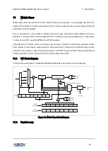


7. Interrupt controller
A96G140/A96G148/A96A148 User’s manual
80
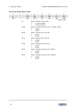
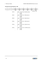
EIFLAG0 (External Interrupt Flag0 Register): C0H
7
6
5
4
3
2
1
0
FLAG7
FLAG6
FLAG5
FLAG4
FLAG3
FLAG2
FLAG1
FLAG0
R/W
R/W
R/W
R/W
R/W
R/W
R/W
R/W
Initial value: 00H
EIFLAG0[7:0]
When an External Interrupt 0-7 is occurred, the flag becomes
‘1’.The
flag is cleared only by writing
‘0’ to the bit. So, the flag should be
cleared by software.
0
External Interrupt0 ~ 7 not occurred
1
External Interrupt0 ~ 7 occurred
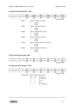
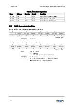
EIPOL0H (External Interrupt Polarity 0High Register): A5H
7
6
5
4
3
2
1
0
POL7
POL6
POL5
POL4
R/W
R/W
R/W
R/W
R/W
R/W
R/W
R/W
Initial value: 00H
EIPOL0H[7:0]
External interrupt (EINT7, EINT6, EINT5, EINT4) polarity selection
POLn[1:0]
Description
0
0
No interrupt at any edge
0
1
Interrupt on rising edge
1
0
Interrupt on falling edge
1
1
Interrupt on both of rising and falling edge
Where n =4, 5, 6 and 7
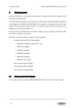
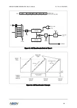
EIPOL0L (External Interrupt Polarity 0Low Register): A4H
7
6
5
4
3
2
1
0
POL3
POL2
POL1
POL0
R/W
R/W
R/W
R/W
R/W
R/W
R/W
R/W
Initial value: 00H
EIPOL0L[7:0]
External interrupt (EINT0, EINT1, EINT2, EINT3) polarity selection
POLn[1:0]
Description
0
0
No interrupt at any edge
0
1
Interrupt on rising edge
1
0
Interrupt on falling edge
1
1
Interrupt on both of rising and falling edge
Where n =0, 1, 2 and 3