


A96G140/A96G148/A96A148 User’s manual
12. Timer 0/1/2/3/4/5
149
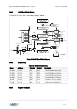
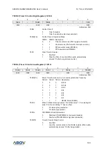
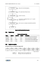
T5CRH (Timer 5 Control High Register): 1010H
7
6
5
4
3
2
1
0
T5EN
–
T5MS1
T5MS0
–
–
–
T5CC
R/W
–
R/W
R/W
–
–
–
R/W
Initial value: 00H
T5EN
Control Timer 5
0
Timer 5 disable
1
Timer 5 enable (Counter clear and start)
T5MS[1:0]
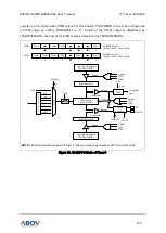
Control Timer 5 Operation Mode
T5MS1 T5MS0 Description
0
0
Timer/counter mode (T5O: toggle at A match)
0
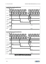
1
Capture mode (The A match interrupt can occur)
1
0
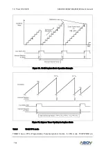
PPG one-shot mode (PWM5O)
1
1
PPG repeat mode (PWM5O)
T5CC
Clear Timer 5 Counter
0
No effect
1
Clear the Timer 5 counter (When write, automatically
cleared “0” after being cleared counter)
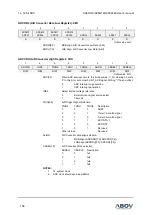
T5CRL (Timer 5 Control Low Register): 1011H
7
6
5
4
3
2
1
0
T5CK2
T5CK1
T5CK0
T5IFR
–
T5POL
–
T5CNTR
R/W
R/W
R/W
R/W
–
R/W
–
R/W
Initial value: 00H
T5CK[2:0]
Select Timer 5 clock source. fx is main system clock frequency
T4CK2
T4CK1 T4CK0 Description
0
0
0
fx/512
0
0
1
fx/128
0
1
0
fx/32
0
1
1
fx/8
1
0
0
fx/4
1
0
1
fx/2
1
1
0
fx/1
1
1
1
HSIRC Direct (32MHz)
T5IFR
When T5 Match Interrupt occurs, this bit becomes
‘1’. For clearing bit,
write
‘0’ to this bit. Writing “1” has no effect.
0
T5 interrupt no generation
1
T5 interrupt generation
T5POL
T5O/PWM5O Polarity Selection
0
Start High (T5O/PWM5O is low level at disable)
1
Start Low (T5O/PWM5O is high level at disable)
T5CNTR
Timer 5 Counter Read Control
0
No effect
1
Load the counter value to the B data register (When write,
automatically cleared
“0” after being loaded)