


A96G140/A96G148/A96A148 User’s manual
16. USART 2
201
becomes normal GPIO or primary function pin.
16.8.5
Asynchronous data reception
To receive asynchronous data frame, the USART2 includes a clock and data recovery unit. The Clock
Recovery logic is used for synchronizing the internally generated baud rate clock to the incoming
asynchronous serial frame on the RXD2 pin.
Data recovery logic samples incoming bits and low pass filters them, and this removes the noise of
RXD2 pin.
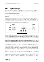
Figure 103 describes sampling process of the start bit of an incoming frame. The sampling rate is 16
times the baud rate for normal mode, and 8 times the baud rate for Double Speed mode (U2X=1). The
horizontal arrows show the synchronization variation due to the asynchronous sampling process. Note
that larger time variation is shown when using the Double Speed mode.
Figure 105. Start Bit Sampling
When the Receiver is enabled (RXE=1), the clock recovery logic tries to find a high to low transition on
the RXD2 line, which is a start bit condition. After detecting the high to low transition on RXD2 line, the
clock recovery logic uses the samples 8, 9, and 10 for Normal mode, and the samples 4, 5, and 6 for
Double Speed mode to decide if a valid start bit is received. If more than 2 samples have logical low
level, it is considered that a valid start bit is detected and the internally generated clock is synchronized
to the incoming data frame. And the data recovery can begin. The synchronization process is repeated
for each start bit.
As described above, when the Receiver clock is synchronized to the start bit, the data recovery can
begin. Data recovery process is almost similar to the clock recovery process. The data recovery logic
samples 16 times for each incoming bits for Normal mode and 8 times for Double Speed mode. It uses
the samples 8, 9, and 10 to decide data value for Normal mode, and the samples 4, 5, and 6 for Double
Speed mode.
If more than 2 samples have low levels, the received bit is considered to a logic 0. If more than 2
samples have high levels, the received bit is considered to a logic 1. The data recovery process is then
repeated until a complete frame is received including the first stop bit. The decided bit value is stored
in the receive shift register in order. Note that the Receiver only uses the first stop bit of a frame.
RxD2
0
0
1
2
3
4
5
6
7
8
9
10
11
12
13 14
15
16
1
2
3
IDLE
BIT0
START
0
1
2
3
4
5
6
7
8
1
2
Sample
(U2X = 0)
Sample
(U2X = 1)