


15. USI
A96G140/A96G148/A96A148 User’s manual
164
The TXCn flag is automatically cleared when the transmit complete interrupt serve routine is executed,
or it can be cleared by writing ‘0’ to TXCn bit in USInST1 register.
When the transmit complete interrupt enable (TXCIEn) bit in USInCR2 register is set and the global
interrupt is enabled, UART transmit complete interrupt is generated while TXCn flag is set.
15.8.3
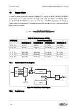
USIn UART parity generator
The parity generator calculates the parity bit for the serial frame data to be sent. When parity bit is
enabled (USInPM1=1), the transmitter control logic inserts the parity bit between the MSB and the first
stop bit of the frame to be sent.
15.8.4
USIn UART disabling transmitter
Disabling the transmitter by clearing the TXEn bit will not become effective until ongoing transmission
is completed. When the Transmitter is disabled, the TXDn pin can be used as a normal general purpose
I/O (GPIO).
15.9
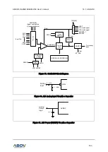
USIn UART receiver
The USART receiver is enabled by setting the RXEn bit in the USInCR2register. When the receiver is
enabled, the RXDn pin should be set to RXDn function for the serial input pin of UART by P4FSR[1:0]
and P4FSR[1:0]. The baud-rate, mode of operation and frame format must be set before serial reception.
In synchronous or SPI operation mode the SCKn pin is used as transfer clock input, so it should be
selected to do SCKn function by P4FSR[5:4] and P2FSR[3:2]. In SPI operation mode the SSn input pin
in slave mode or can be configured as SSn output pin in master mode. This can be done by setting
USInSSEN bit in USInCR3 register.
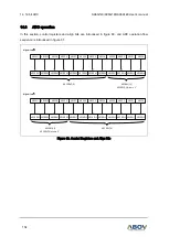
15.9.1
USIn UART receiver RX data
When UART is in synchronous or asynchronous operation mode, the receiver starts data reception
when it detects a valid start bit (LOW) on RXD0 pin. Each bit after start bit is sampled at pre-defined
baud-rate (asynchronous) or sampling edge of SCKn (synchronous), and shifted into the receive shift
register until the first stop bit of a frame is received. Even if there’s the second stop bit in the frame, the
second stop bit is ignored by the receiver. That is, receiving the first stop bit means that a complete
serial frame is presented in the receiver shift register and contents of the shift register are to be moved
into the receive buffer. The receive buffer is read by reading the USInDR register.
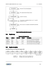
If 9-
bit characters are used (USInS[2:0] = “111”), the n
inth bit is stored in the USInRX8 bit position in
the USInCR3 register. The ninth bit must be read from the USInRX8 bit before reading the low 8 bits
from the USInDR register. Likewise, the error flags FEn, DORn, PEn must be read before reading the
data fr
om USInDR register. It’s because the error flags are stored in the same FIFO position of the
receive buffer.