background image

EN 

-

 6

5 Operation

ABITIG

®

 Little

4.3

Equipping the welding torch, Fig. 1

A gas lens can also be used instead of the collet housing. Owing to its design, it will producealaminar gas flow.

4.3.1

ABITIG

®

 Little 24 G/24 W/9/17/25:

1

Screw the collet housing with collet into the torch body.
A gas lens can also be used instead of the collet housing. Owing to its 
design, it will producealaminar gas flow.

2

Screw the back cap with the tungsten electrode into the torch body.

3

Screw on the gas nozzle.

Step 2 is not required with the ABITIG

®

 Little 24 G and 24 W

4.3.2

ABITIG

®

 Little 150/260 W:

1

Insert the electrode holder into the torch body.

2

Screw the back cap with the tungsten electrode into the torch body.

3

Screw on the gas nozzle.

4.3.3

ABITIG

®

 Little 90/180 W:

1

Insert the electrode holder into the torch body.

2

Screw the back cap with the tungsten electrode into the torch body.

3

Push on the gas nozzle.

4.4

Shortening the tungsten electrode

The electrode type is set by EN ISO 6848. 
The electrode length depends on the torch type.

The welding performance is affected by the selection of the tungsten 
electrode and by wear.Asmooth, groove-free sharpened end of the tungsten 
electrode hasapositive effect on the welding result.

4.5

Sharpening tungsten electrodes, Fig. 3

Sharpening the tungsten electrode depends on wear and must therefore be 
carried out when required.
► When sharpening the tungsten electrode, useasharpening device with 

the following properties:

— Diamond disc

— Point sharpened longitudinally through the centre axis
— Automatic regulation of the tungsten electrode drive by gravity
— Can be set for all electrode diameters
— Offers continuous angle adjustment

4.6

Connecting the cable assembly

1

Plug the cable assembly connector into the welding power source and 
secure it withaconnection nut.

2

Properly mount the connections for coolant supply/return, shielding gas 
and control lead connector.

4.7

Connecting the coolant hoses

1

Connect the coolant supply (blue) and coolant return (red).

2

Check the coolant’s minimum fill level.

► Recommendation: Use ABICOR BINZEL coolants from the BTC range.

► To prevent damage to the welding device, do not use deionised or 

demineralised water.

► Bleed the coolant circuit upon commissioning and when replacing the 

cable assembly.

4.8

Bleeding the coolant circuit

1

Place the collection receptacle under the connection for the coolant 
return (red).

2

Disconnect the coolant return hose from the cooling unit and hold it over 
collection receptacle.

3

Seal the coolant return hose’s opening.

4

Abruptly open then seal the coolant return hose’s opening several times 
until the coolant flows into the collection receptacle continuously and 
without air bubbles.

5

Reconnect the coolant return hose to the cooling unit.

4.9

Connecting the shielding gas and setting the gas volume

The type and amount of shielding gas used depend on the welding task and 
the gas nozzle geometry.

1

Select the appropriate shielding gas for the welding task.

2

Briefly open the valve on the gas supply then close it again to air-blast 
away any dirt on the connector.

3

Connect the shielding gas to the welding device as per the 
manufacturer’s instructions.

4

Adjust the shielding gas volume to the gas nozzle used and the welding 
task and save the setting.

5 Operation

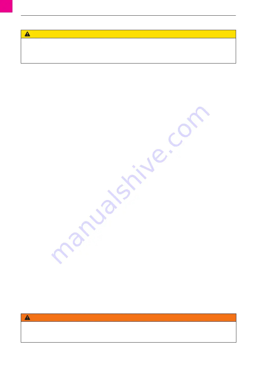
CAUTION

Risk of injury from the sharpened electrode

The sharpened electrode is pointed and can cause puncture injuries.
► Keep your hands away from the electrode tip.
► Hold the electrode tip away from your body.
► Wear the correct protective gloves.

WARNING

Risk of injury due to electromagnetic fields

The device can produce electromagnetic fields that could impact the proper function of cardiac pacemakers and implanted defibrillators.
► Do not use the device if you haveapacemaker or an implanted defibrillator.
► Only use the device in industrial zones in accordance with DIN EN 61000

-

6

-

3.

Summary of Contents for ABITIG Little 24G

Page 1: ...binzel abicor com DE Original Betriebsanleitung EN Original operating instructions FR Mode d emploi d origine ES Manual de instrucciones original ABITIG Little DE WIG Schwei brenner EN TIG welding to...

Page 2: ...1 ABITIG Little 24 G 24 W 9 17 25 ABITIG Little 90 180 W ABITIG Little 150 260 W 1 2 3 1 2 1 3 3 2 1 1 2 2 ABITIG Little 24 G 24 W 9 17 25 ABITIG Little 90 180 W ABITIG Little 150 260 W A B C D E F A...

Page 3: ...Spannh lse E Gasd se F Elektrodenhalter EN A Back cap B Torch body C Tungsten electrode D Collet E Gas nozzle F Electrode holder FR A Coiffe B Corps de torche C lectrode tungst ne D Pince tau E Buse g...

Page 4: ...n Zweck in der beschriebenen Art und Weise verwendet werden Beachten Sie dabei die Betriebs Wartungs und lnstandhaltungsbedingungen Jede andere Verwendung gilt als nicht bestimmungsgem Eigenm chtige U...

Page 5: ...Haaren ein Haarnetz Tragen Sie im Betrieb und in Verbindung mit dem Schwei prozess Schutzbrille Schutzhandschuhe und ggf Atemmaske 2 6 Sicherheitshinweise zur Verwendung berschreiten Sie nicht die in...

Page 6: ...sche Schwei brennerdaten EN 60974 7 Typ K hlart Belastung ED Elektoden Gasdurchfluss K hlung Vorlauf temperatur Durchfluss DC AC1 1Gem EN 60974 7 ist der Wert f r Wechselstrom AC mit 70 des gepr ften...

Page 7: ...kraft F r alle Elektrodendurchmesser einstellbar Stufenlose Winkeleinstellung 4 6 Schlauchpaket anschlie en 1 Schlauchpaketanschluss in Schwei stromquelle einstecken und mit Anschlussmutter sichern 2...

Page 8: ...t berpr fen und reinigen lassen bzw die Bauteile gegebenenfalls wechseln Bei sehr h ufigem Einsatz und oder sehr hohen Stromst rken und oder erkennbarer Abnutzung das Intervall verk rzen WARNUNG Verle...

Page 9: ...ndsetzung des Produktes durch Anwender oder Dritte Verschlei teile fallen generell nicht unter die Gew hrleistung Ferner haftet ABICOR BINZEL nicht f r Sch den die durch die Verwendung unseres Produkt...

Page 10: ...load data specified in the documentation Excessive loads lead to irreparable damage Do not make any constructive changes to the product During welding work outdoors use suitable protection against th...

Page 11: ...ion against the weather conditions 2 7 Classification of the warnings The warnings used are divided into four different categories and are indicated prior to potentially dangerous work steps Depending...

Page 12: ...welding torch data EN 60974 7 Type Type of cooling Load Duty cycle Electrode Gas flow rate Cooling Supply temp Flow DC AC1 1Pursuant to EN 60974 7 the alternating current AC must be specified with 70...

Page 13: ...ons for coolant supply return shielding gas and control lead connector 4 7 Connecting the coolant hoses 1 Connect the coolant supply blue and coolant return red 2 Check the coolant s minimum fill leve...

Page 14: ...ubject to wear and soiling Asaresult they must undergo regular maintenance and cleaning Torch body Gas nozzle Tungsten electrode Back cap Electrode holder 7 2 Annual maintenance by an electrician Have...

Page 15: ...repaired improperly by the user orathird party Wear parts are excluded in general from the warranty In addition ABICOR BINZEL is not liable for damage caused by using our products Questions about war...

Page 16: ...ansformations ou modifications effectu es de mani re arbitraire pour augmenter la puissance sont interdites Ne d passez pas les capacit s maximales indiqu es dans la documentation Les surcharges provo...

Page 17: ...rovoquent des d g ts irr parables Il est interdit d apporter des modifications constructives cet appareil En cas d utilisation l air libre une protection ad quate contre les influences atmosph riques...

Page 18: ...Selon EN 60974 7 la valeur du courant alternatif C A correspond 70 de la valeur test e en courant continu C C Max Min A A mm l min C l min 9 Air 110 80 35 0 5 1 6 5 12 17 Air 140 100 35 0 5 2 4 7 15 9...

Page 19: ...rez le raccordement du faisceau dans la source de courant de soudage et serrez le l aide de l crou de raccordement 2 Raccordez correctement l amen e et le retour de liquide de refroidissement l alime...

Page 20: ...torche Buse gaz lectrode tungst ne Coiffe Porte lectrode AVERTISSEMENT Risque de blessure li aux champs lectromagn tiques Le dispositif peut g n rer des champs lectromagn tiques qui peuvent perturber...

Page 21: ...ces de rechange et d usure autres que les pi ces ABICOR BINZEL d origine et en cas de r paration inappropri e du produit par l utilisateur ou des tiers Les pi ces d usure ne sont g n ralement pas cou...

Page 22: ...cribe Observe tambi n las condiciones para el servicio el mantenimiento y la reparaci n Cualquier otra utilizaci n se considera como no conformealo prescrito Las reformasomodificaciones para el increm...

Page 23: ...rgo utilice una redecilla Durante la operaci n y el proceso de soldadura utilice gafas protectoras guantes de protecci n y en caso necesario m scara de respiraci n 2 6 Instrucciones de seguridad para...

Page 24: ...dadura EN 60974 7 Tab 3 Datos espec ficos de la antorcha de soldadura EN 60974 7 Tipo Tipo de refrigeraci n Carga C T electrodos Caudal de gas Refrigeraci n Temp de entrada del refrigerante Caudal CC...

Page 25: ...o de tungsteno El tipo de electrodo est determinado seg n EN ISO 6848 La longitud del electrodo depende del tipo de antorcha El electrodo de tungsteno seleccionado y el desgaste influyen sobre el comp...

Page 26: ...ujetar el arco sin movimiento longitudinal sobre los bordes del materialasoldar hasta que se forme un ba o de fusi n 8 Llevar la antorcha de soldadura uniformemente sobre la longitud entera de la sold...

Page 27: ...de utilizar piezas de recambio que no sean piezas originales de ABICOR BINZELoen caso de que el usuariooun tercero haya reparado el producto de forma inadecuada Las piezas de desgaste en general se en...

Page 28: ...ne Winwick Quay Warrington WA2 8UA UK T 44 1925 65 39 44 F 44 1925 65 48 6 info binzel abicor co uk T E C H N O L O G Y F O R T H E W E L D E R S W O R L D Download mobile documentation 1 Scan QR code...

Reviews: