


Page 4
–14
2104349 rev. AD
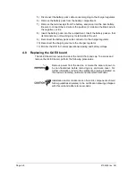
4) Gain access to the rear termination board by loosening the countersunk hex
socket locking set screw in the rear end cap. Use a 1/16” hex wrench to
perform this task. Upon completion, unscrew the end cap.
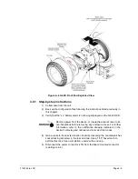
5) Upon unscrewing the end cap, the user will see the termination board (see
–5). Using a ¼” socket wrench, unscrew the four socket mounting
screws that hold the termination board in place.
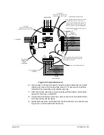
6) Depending on the configuration that the user selected from the factory,
remove either the USB cable (J4), Ethernet cable (J7) or MMI cable (J21).
7) Next, remove the Comm 1 (J19), Comm 2 (J20) and power (J16)
connectors.
8) Upon completion, remove the ribbon cable from the J1 connector (Figure 4
9). This will enable the user to remove the termination board from the G4
EX device.
Figure 4
–9 Termination board secondary component side
9) Take the replacement termination board and attach the ribbon cable to the
J1 connector.
Please note that the ribbon cable pin 1 wire is red. The red
edge (pin 1) of the cable should plug into the outer most
edge of the connector (pin 1).
10) Depending on the configuration that the user selected from the factory,
attach either the USB cable (J4), Ethernet cable (J7) or MMI cable (J21) to
their respective connection.
11) Next, attach the Comm 1 (J19), Comm 2 (J20) and power (J16) connections
to their respective connectors.
12) Upon completion, take the four socket mounting screws, and attach the
termination board in the G4 EX device.
J1
50
2
49
1
Summary of Contents for XSeries G4 6200
Page 42: ......
Page 61: ...2104349 rev AD Page 2 19 Figure 2 18 G4 EX to UPS ...
Page 62: ......
Page 130: ......
Page 163: ...2104349 rev AD Page 33 ...