


2104349 rev. AD
Page 4
–13
4.9
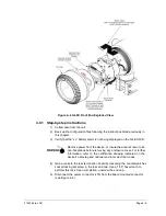
Replacing the G4 EX termination board
The termination board is mounted inside of the G4 EX back end cap. To access
and remove the display board, perform the following procedures.
Figure 4
–8 G4 EX Back End Exploded View
4.9.1 Step-by-step instructions
1) Collect data from the unit.
2) Back up the configuration files following the instructions listed previously in
this chapter.
3)
Verify that the “LL” battery alarm is not being displayed on the G4 EX LCD.
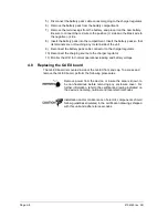
Remove power from the device, or insure the area is known to be
non-hazardous before removing any enclosure cover. For further
information, refer to the certification drawing indicated on the
device’s nametag and national and local electrical codes.
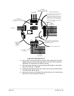
Term Board
Ribbon Cable
Note: The single red wire on the cable goes
to Pin 1 of both connectors
MMI Connector
Rear Cap
Stand-off
(4 places)
Summary of Contents for XSeries G4 6200
Page 42: ......
Page 61: ...2104349 rev AD Page 2 19 Figure 2 18 G4 EX to UPS ...
Page 62: ......
Page 130: ......
Page 163: ...2104349 rev AD Page 33 ...