


647647/001 - M3371 - 2000/08/30 it-en - 45/100
– chiudere il sezionatore di terra girando in senso orario la leva
di manovra;
– estrarre la leva di manovra (13) dalla sede del sezionatore;
– controllare dall’oblo (6) che l’indicatore di posizione del
sezionatore di terra indichi la chiusura dello stesso “I”;
– aprire la porta della cella interruttore (1) tirando la maniglia
verso l’alto.
(2) Passaggio dalla posizione di “sezionato in prova” a quella
di “sezionato” (sconnessione degli ausiliari) (fig. 45)
– sbloccare il connettore mobile (1) ed estrarlo dalla presa fissa
del contenitore (2);
(3) Passaggio dalla posizione di “sezionato” a “estratto”
– accostare il carrello al quadro (fig. 44a);
– inserire la staffa di aggancio (4) fig. 44b - c e bloccare le ruote
(3) (fig. 44a);
– spostare contemporaneamente le due maniglie (5) (fig. 44d)
verso l'asse mediano dell’ interruttore e contemporanea-
mente tirare progressivamente tramite le maniglie l’ interrut-
tore verso l’esterno sul carrello;
– lasciare libere le maniglie e continuare l’estrazione finché
l’interruttore si blocca con le maniglie (fig. 44a) che scattano
lateralmente bloccando l’interruttore sul carrello.
– sbloccare le ruote (3) (fig. 44a) e sollevare la staffa di aggan-
cio (4) (fig. 44f);
– sollevare la staffa di aggancio (4) (fig. 44f) e allontanare il
carrello dal quadro.
6.2.2. Scomparto TV
La messa in servizio e fuori servizio del carrello TV
deve essere effettuata solo a porta chiusa.
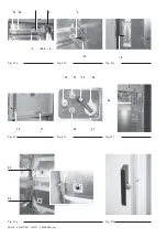
a) Manovra di inserimento del carrello nello scomparto
– aprire la porta dello scomparto tirando la maniglia (fig. 47m)
(3) verso l’alto;
– inserire le guide supplementari sinistra e destra (fig. 47a)
nelle cave laterali come in fig. 47b;
– sollevare la parte anteriore del carrello TV e inserire le ruote
anteriori nelle guide supplementari (fig. 47c);
– spingere il carrello verso il fondo, sollevare la parte posteriore
e inserire le ruote posteriori nelle cave delle guide supple-
mentari (fig. 47d);
– spingere il carrello verso il fondo sino a che si blocca (fig. 47e);
– estrarre le guide supplementari sinistra e destra (fig. 47f);
– agganciare la portella (fig. 47g) e inserire il collegamento di
messa a terra della portella;
– serrare le viti di fissaggio della portella (fig. 47h - fig.47i);
– spostare verso sinistra il piolo liberando il foro di innesto della
leva di manovra (2) (fig. 47l);
– ruotare in senso orario l’attuatore del chiavistello di blocco
della portella (1) (fig. 47l);
– chiudere la porta della cella spingendo la maniglia (fig. 47m)
(3) verso il basso.
– close the earthing switch turning the operating lever clock-
wise;
– withdraw the operating lever (13) from the earthing switch
seat;
– through the inspection window (6) make sure that the earthing
switch is closed (indicator in the “I” position);
– open the circuit-breaker compartment door (1) pulling the
handle upwards.
(2) Switching from “isolated for test” to “isolated” position
(auxiliary circuit disconnection) (fig. 45)
– unlock the mobile connector (1) and withdraw the latter from
the enclosure fixed socket (2);
(3) Switching from “isolated” to “withdrawn” position
– draw the truck close to the switchboard (Fig. 44a);
– insert the hooking bracket (4) (Fig. 44b-c) and block the
wheels (3) (fig. 44a);
– move the two handles (5) (fig. 44d) at the same time towards
the circuit-breaker centre and by means of the handles
gradually pull the circuit-breaker outside on the truck;
– release the handles and continue withdrawal until the circuit-
breaker stops (fig. 44a) and the handles trip sideways thus
locking the circuit-breaker on the truck;
– unlock the wheels (3) (fig. 44a) and lift the hooking bracket (4)
(fig. 44f);
– lift the hooking bracket (4) (fig. 44f) and remove the truck from
the switchboard.
6.2.2. VT compartment
Putting the VT truck in and out of service must be
carried out with the door closed
a) Racking truck into the compartment
– open the compartment door pulling the handle (3) (fig. 47m)
upwards;
– insert the left and right additional guides (fig. 47a) in the lateral
slots as in fig. 47b;
– lift the VT truck front part and insert the front wheels in the
additional guides (fig. 47c);
– push the truck backwards, lift the rear part and insert the rear
wheels in the additional guide slots (fig. 47d);
– push the truck backwards until it is blocked (fig. 47e);
– remove the left and right additional guides (fig. 47f);
– hook the door (Fig. 47g) and insert the door earthing connec-
tion;
– tighten the door fixing screws (fig. 47h-fig. 47i);
– move the pin leftwards removing it from the slot of the
operating lever (2) (fig. 47l);
– turn the lever of the door locking bolt clockwise (1) (fig. 47l);
– close the compartment door pushing the handle (3) (fig. 47m)
downwards.
!
!