


42/100 - 647647/001 - M3371 - 2000/08/30 it-en
2
1
3
4
4
6
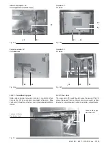
Fig. 44c
6.2. Manovre di inserzione ed estrazione
delle apparecchiature nel quadro
•
Qualora vengano fatte manovre con interruttore
estratto dal quadro prestare la massima attenzio-
ne alle parti in movimento.
•
L'interruttore deve essere inserito nell'unità solo
in posizione di aperto, l'inserimento e l'estrazione
deve essere graduale per evitare urti che possono
deformare gli interblocchi meccanici.
6.2.1. Apparecchi (interruttori e contattori)
Nelle istruzioni di seguito riportate è rappresentato l’interruttore
HD4. Le istruzioni sono comunque valide anche per interruttori
VD4 e contattori V-Contact.
a) Manovra di inserzione
(1) Passaggio da interruttore estratto alla posizione di “sezio-
nato”
– sollevare l’apparecchio (2) (fig. 44a) e adagiarlo sul carrello
di movimentazione (1) (fig. 44a) seguendo le istruzioni indi-
cate al par. 4 “Movimentazione dell’interruttore con carrello”;
– aprire la porta della cella interruttore;
– accostare il carrello al quadro (fig. 44a)
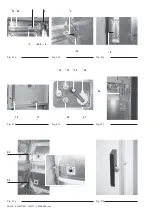
– inserire la staffa di aggancio (4) (fig. 44b - c), e bloccare le
ruote (3) (fig. 44a);
– sganciare l’interruttore dal carrello spostando contempora-
neamente le due maniglie (5) (fig. 44d) verso l'asse mediano
dell’ interruttore e contemporaneamente spingere progres-
sivamente tramite le maniglie l’ interruttore verso il fondo del
quadro, finché l’interruttore si blocca con le maniglie (5) (fig.
44e) che scattano lateralmente inserendosi nelle cave (6)
(fig. 44b);
– sbloccare le ruote (3) (fig. 44a) sollevare la staffa di aggancio
(4) (fig. 44f) e allontanare il carrello dal quadro.
Assicurarsi che le maniglie siano scattate lateral-
mente (blocchi orizzontali del carrello inseriti nel
contenitore).
Fig. 44a
Fig. 44b
6.2. Apparatus racking in/out
•
Should any operation be carried out while the cir-
cuit-breaker is withdrawn from the switchboard,
pay the utmost attention to the moving parts.
•
The circuit-breaker must be inserted into the unit
only in the open position; its racking in/out must be
gradual, so as to safeguard the mechanical inter-
locks against any deforming impact.
6.2.1. Apparatus (circuit-breakers and contactors)
The following instructions refer to HD4 circuit-breakers but they
are valid for VD4 circuit-breakers and V-Contact contactors as
well.
a) Racking in
(1) Switching from circuit-breaker withdrawn to “isolated” posi-
tion
– lift the apparatus (2) (fig. 44a) and place it on the handling
truck (1) (fig. 44a), following the instructions in par. 4 “Circuit-
breaker handling by means of truck”;
– open the door of the circuit-breaker compartment;
– draw the truck close to the switchboard (fig. 44a);
– insert the hooking bracket (4) (fig. 44b - c), and block the
wheels (3) (fig. 44a);
– release the circuit-breaker from the truck by moving the two
handles (5) at the same time (fig. 44d) towards the circuit-
breaker centre axis and at the same time gradually pushing
the circuit-breaker handles towards the back of the switch-
board until the circuit-breaker locks with the handles (5) (fig.
44e) clicking laterally, inserting themselves into the slots (6)
(fig. 44b);
– unlock the wheels (3) (fig. 44a), lift the hooking bracket (4) (fig.
44f) and remove the truck from the switchboard.
Make sure that the side locking handles properly
engage with the relevant slots. (the horizontal truck
blocks must be inserted into the enclosure).
!
!
!
!