


35
1ZSE 5492-118 en, Rev. 4
fm_00002
TC_00149
5 Final assembly
10. Pull down the protective tube SA15 and mount the hose clip SA10. See Fig. 31. Note
the clearance for draining. (Min 3 mm, max 5 mm).
11. Remount the cover of the gear box on the top of the on-load tap-changer.
Fig. 31.
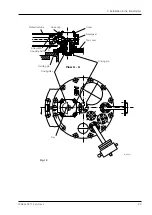
Earthing symbol
Key in the bevel gear
140
o
125
o
SA10
SA10
SA15
SA16
SA10
SA15
Min. 3, max 5 mm
Fig. 30. Adjustment of bevel gear.