


19
1ZSE 5492-118 en, Rev. 4
fm_00204
3 Installation in the transformer
3.2.2 Mounting of the on-load tap-changer when transformer ratio measurement is carried out
after drying
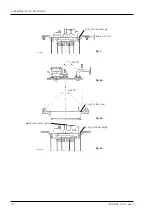
Mounting to the ”yoke-fork” of the transformer. See Fig. 9.
1. Loosen all the twelve bolts and washers in the top cover and lift the cover carefully min.
100 mm straight upwards before moving it in horizontal direction. The bevel gear and
the pipe may not be damaged when lifting. If a crane is used arrange the straps accord-
ing to Fig. 8a.
2. Remove the upper part of the top section by loosening the twelve M8-socket head cap
screws inside it. Keep the flange, the cover, the O-rings and the sealing for the suction
pipe, see Fig. 8 and store them temporarily on a dustfree place.
NOTE: The gear mechanism on the gear base plate needs not and shall not be re-
moved, because it is fixed in the lower part.
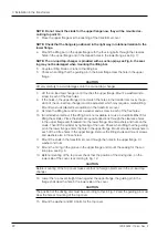
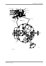
3.
When lifting the on-load tap-changer onto the ”yoke-fork” it is recommended that
lifting eyes M12 are mounted in the lower flange.
NOTE: Check that the on-load tap-changer is positioned in the right way in rotational
relation to the transformer cover, before connection of conductors according to sec-
tion 4.3.
NOTE: Spacers (for example of wood) can be placed between the ”yoke-fork” and
the lower flange. The connectors can hereby be mounted on the right final height.
The spacers must be removed before mounting of the on-load tap-changer onto the
transformer cover. See Fig. 10.
max 90
o
Fig. 9.