


17
1ZSE 5492-118 en, Rev. 4
3 Installation in the transformer
3.2.1 Mounting of the on-load tap-changer when transformer ratio measurement is carried out
before drying
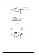
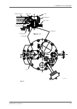
Mounting to the ”yoke-fork” of the transformer, see Fig. 6.
1.
Mount the on-load tap-changer on the transformer’s ”yoke-fork”, the lifting lugs on the
upper part can be used, see Fig. 6. Handle with care without damaging the terminals
and tie-in resistors (if any).
NOTE: Check that the on-load tap-changer is positioned in the right way in rotational
relation to the transformer cover, before connection of conductors.
2. Connect the conductors according to section 3.1.1.
3. Transformer ratio measurement.
4. The on-load tap-changer can be operated by turning the shaft of the bevel gear. Use a
special hand crank, LL 117 016-M.
5. Two turns in clockwise direction (seen against the shaft end) for RAISE or two turns
anticlockwise for LOWER operation, will be equal to one switching between two taps.
Check the order documents if otherwise is stated according to the direction of rotation.
CAUTION
The on-load tap-changer should be operated through the whole operating range, both in
lower and raise direction, when carrying out ratio measurement.
The end positions must not be overrun during ratio measurement. When operating the on-
load tap-changer without drive system, check the designation of the end positions on the
single-phase diagram and watch the position indicator in the bevel gear in order to avoid
overrunning of the end position.
Watch the voltmeter during the on-load tap-changer operations. No fast voltage drops may
occur during operation. If such drops occur, the on-load tap-changer is not correctly con-
nected to the winding.
6. After the measurement, the position of the on-load tap-changer must be replaced to
the same position as the motor-drive mechanism indicates, check in the indicator win-
dow on the top cover.
7. Loosen all the twelve bolts and washers in the top cover and lift the cover carefully min.
10 cm straight upwards before moving it in horizontal direction. The bevel gear and the
pipe may not be damaged when lifting. If a crane is used arrange the straps according
to Fig. 8a.
8. Remove the upper part of the top-section by loosening the twelve M8-socket head cap
screws inside it. Keep the flange, the cover, the O-rings and the sealing for the suction
pipe, see Figs. 6 and 8 and store them temporarily on a dustfree place.
9. The on-load tap-changer and the transformer is now ready for drying. Follow the in-
structions in chapter 5.
NOTE: The gear mechanism on the gear base plate needs not and shall not be re-
moved, because it is fixed in the lower part.
NOTE: Spacers (for example of wood) can be placed between the ”yoke-fork” and
the lower flange. The connectors can hereby be mounted on the right final height.
The spacers must be removed before mounting of the on-load tap-changer onto the
transformer cover. See Fig. 7.