


31
1ZSE 5492-118 en, Rev. 4
TC_00238
TC_00238
5 Final assembly
5.3.1 Mounting of horizontal drive shaft
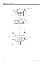
1. Mount the bevel gear SA21 on the transformer, with O-ring SA20, four clamps SA17,
hexagon head bolts M10, SA18 and washers SA19, see Fig. 16.
2. Determine the dimension K1 between the spherical shaft ends, see Fig. 17.
3. Cut the square shaft SA22 to dimension = K1 minus 6 mm. Remove the burrs.
4. Cut the protective tubes SA23 and SA24 in the unslotted end so that both of them get
the same length LB1 according to the table 2 below.
NOTE: Protective tubes with slotted ends shall be used.
Table 2. Length dimension for LB1.
K1 = 190 to 290 mm
K1 = 291 to 600 mm
K1 = greater than 600 mm
LB1 =
K1+180 mm
2
LB1 =
K1+210 mm
2
LB1 =
K1+410 mm
2
Example: K1 measured to 390 mm. LB1 is then =
390+210
=
600
= 300 mm
2
2
NOTE: If K1 is greater than 600 mm the mounted tubes shall overlap each other at
least 300 mm. Dismounting and inspection of the couplings shall be possible when
one of the tubes is pushed into the other.
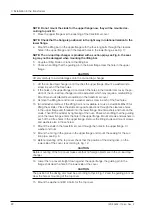
5. Fit two coupling halves, SA11, on one end of the square shaft with six screws SA12
and washers, SA13. Push the shaft to the bottom of the fitting in the coupling halves.
Tighten the two screws A first and then the others, see Fig. 19. Put on the two protec
-
tive tubes, SA23 and SA24, the slotted ends outwards, and two hose clips SA10, see
Fig. 18.
SA10
SA23
SA11
SA24
SA14
K1
SA 21
LB1
Fig. 17.
Fig. 18.