background image

4 8  

S P I R I T

I T

  F L O W - X

  I N S T R U C T I O N   M A N U A L   |   I M / F L O W X - E N  


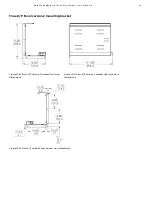
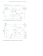
Figure 10-23  Cut out Door - Front installation, horizontal Flow-X/C 


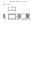
Flow-X/R Rack mount enclosure 


Figure 10-24 Flow-X/R Side view dimensions   


Figure 10-25 Flow-X/R Side view dimensions 


Summary of Contents for SpiritIT Flow-X

Page 1: ... Gas Metric application IIC Liquid Metric application IID Gas US customary units application IIE Liquid US customary units application Volume III The manuals for solutions that exceed our standard applications This volume consists of 1 part IIIB Function referencere For more information All publications of SpiritIT Flow X are available for free download from Search for SpiritIT Flow X instruction ...

Page 2: ...reak out board connection details 21 Connection diagrams 22 Honeywell Enraf Calibron small volume prover 27 Serial communication 27 Proving signals 28 Earth ground connection 30 7 Operator Panels 32 Introduction 32 Flow X P Flow X C touch screen 32 Touchscreen panel PC 32 Flow X M LCD display 32 SpiritIT Flow X web interface 32 Graphical User Interface Layout 33 8 Software 34 Introduction 34 Set u...

Page 3: ... presented to assist in enclosure selection In the next chapters fully detailed information is given on all installation aspects In chapter 4 Mechanical installation the mechanical details are given for all models In chapter 5 Electrical installation electrical details are provided typical loop diagrams communication power supply earthing Chapter 6 briefly describes the operator panels Chapter 7 b...

Page 4: ... to interface with the control system in graphic form It may contain trends alarm summaries pictures and animations I O Input Output IEEE Institute for Electrical and Electronics Engineers ISO International Standards Organization MMI Man Machine Interface see HMI MIC Machine Identification Code License code of Spirit IT Flow X which uniquely identifies you computer OEM Original Equipment Manufactu...

Page 5: ...allocation Peer to peer A type of network in which each workstation has equivalent capabilities and responsibilities This differs from client server architectures in which some computers are dedicated to serving the others Peer to peer networks are generally simpler but they usually do not offer the same performance under heavy loads Peer to peer is sometimes shortened to the term P2P Polling A me...

Page 6: ...8 2 2 IEC 60068 2 3 IEC 60068 2 31 IEC 60068 2 36 IEC 60654 2 IEC 61000 4 2 2008 IEC 61000 4 3 2006 A1 2007 A2 2010 IEC 61000 4 4 2012 IEC 61000 4 5 2015 A1 2017 IEC 61000 4 6 2014 IEC 61000 4 8 2009 IEC 61000 4 17 1999 A1 2001 A2 2008 IEC 61000 4 29 2000 IEC 61000 6 2 2016 IEC 61000 6 4 2001 A1 2011 For compliance with IEC 61000 4 4 in case of a flow meter providing a pulse output signal the Flow...

Page 7: ...42 Open collector max 100 Hz Frequency Outputs 42 42 Open collector max 10 kHz Only available for Flow X C device type Sphere 42 42 Supports 1 2 and 4 detector configurations mode Signal type v1 Nr3 v2 Nr3 Description detector inputs 0 5ms detect update rate Analog Outputs 4 4 Analog output for flow control pressure control 4 20mA outputs floating Prover Outputs 12 12 Pulse output for proving appl...

Page 8: ...play with 4 lines for local display of measured calculated data The Flow X S may be mounted in 3 ways Horizontally on Din rail vertically on Din rail and Wall mounted Figure 3 6 Flow X S Single enclosure Flow X K This is a single stream DIN rail enclosure with standard 37 pole D Sub type connectors for field connection Interfaces include dual Ethernet with built in web server via RJ45 connectors I...

Page 9: ...figuration manual Break out board Flow X B The Flow X B break out board allows for convenient connection to the measurement and control signals and protects the flow computer from harmful field signals For fully wired I O two Flow X Bs are required per module Figure 3 9 Flow X B break out board Advantages The SpiritIT Flow X product suite provides a flexible scalable platform to create your flow m...

Page 10: ... a mains supply cord 4 This product is designed and constructed to withstand the forces encountered during normal use Use of the product other than as a flow computer or failure to install the product in accordance with these Instructions product modifications or repair could Cause damage to the product property Cause injury or fatality to personnel Invalidate the marking 5 Spirit IT Flow X produc...

Page 11: ...urces and prevent any potential negative effects on human health and the environment which could otherwise arise from inappropriate waste handling Information for waste treatment facilities In accordance with WEEE 2 Annex VII the following components need to be removed from the different Flow X products and treated separately Model Product number Components Flow X M 6557 xxxx xxxx 1 x Digital boar...

Page 12: ...ving functionality may also be calculated in any module in the same enclosure including the Flow X P Panel display module Special consideration applies to serial ports Every module has 2 serial ports If more ports are required the Flow X P may be considered as it has 3 extra serial ports Alternatively a second module may be added in a Flow X R rack enclosure to provide more serial communication po...

Page 13: ...and feel that it is possibly less than optimum please contact our local vendor or our headquarters to discuss your ideas One of the design goals of the SpiritIT Flow X product suite was scalability customers do not want to pay for hardware they don t use Our modular concept and the available enclosures ensure that your hardware investment is tailored to your specific needs to the maximum extent We...

Page 14: ...nd the screw fixes the two together Figure 5 2 Flow X P Figure 5 3 Flow X P mounted Mounting bracket side view All connectors for power field wiring and communication are located at the back of the Flow X P For each module 2 sub D connectors 37 pin contain all field signals Additional connectors exist for 3 the serial ports of the display module and 2 Ethernet RJ 45 connections A 24VDC Power conne...

Page 15: ... Minimal Distance around Flow X C Brackets in mm Blanking Plate The installtion of the Flow X C can be finished with an blanking plate The measurements for the cut out of the blanking plate can be found on page 45 The maximum distance the Flow X C can come out of the bracket is 23 mm Figure 5 11 Maximum distance of the Flow X C out of the Bracket Flow X C installation example instructions The inst...

Page 16: ...1U 8U 9U It is possible to place three vertical Flow X Cs next to each other and only one horizontal Flow X C on a shelf The precise dimensions can be found on page 45 Shelf Door Installation Flow X Cs can be installed into the door of the standard cabinets of Rittal TS CM and AE The only width of the cabinet door that is usable is 800 mm Figure 5 16 Installation of Flow X C Bracket on to a cabine...

Page 17: ...assignments see page 20 Figure 5 19 Mounting options for Flow X S Figure 5 20 Flow X S mounting sequence DIN rail vertical position Flow X K The single module Flow X K may be mounted on Din rail or directly on a backplane wall The connections are made through 2 sub D connectors There is one power connector and 2 Ethernet RJ 45 connections below the module See page 18 for connector details Note the...

Page 18: ...e 39 pin D sub connectors are the serial ports of the Display module These ports may be used to communicate to devices such as a gas chromatograph or a DCS In Flow X P version 1 Com 1 is RS 232 only Com 2 and Com 3 may be individually configured for RS 232 or RS 485 In Flow X P version 2 Com 3 is RS 232 only and Com 1 and Com 2 are configurable For connector details see page 20 LAN1 and LAN2 are E...

Page 19: ...tion on the connectors of the Flow X B see chapter Break out board connection details on page 21 Enclosure connector details Power supply The SpiritIT Flow X flow computer provides redundant power connections that may be connected to two power supplies The two power supplies may operate independently and there is no need for a redundant power supply When the in use power supply fails the flow comp...

Page 20: ...le must have a female connector The 9 pin D sub male connectors have the following pin connections Figure 6 5 9 pin D sub connector pin numbering Pin X P v1 COM 1 X P v2 COM 3 X C COM 3 X P v1 COM 2 X P v1 COM 3 X P v2 COM 1 X P v2 COM 2 RS 232 only 232 485 2wire 485 4 wire 1 Rx 2 Rx Rx Rx 3 Tx Tx Sig Tx 4 Sig Tx 5 0 V 0 V 6 7 RTS 8 CTS 9 Table 6 4 9 pin D sub connector pin connections for Flow X ...

Page 21: ...RS 485 2 wire RS 485 4 wire The Flow X B does not contain protection serial communication signals PRT inputs A Flow X B has one PRT connection The signals are combined in one 4 pin connector The available PRT connector pins are Function PRT_PWR PRT_SIG Function PRT_SIG PRT_PWR The Flow X B does not contain protection of the PRT input signals Analog inputs Three analog input connections are availab...

Page 22: ...d or DIG_GND These connections are not protected individually A pull up resistor in combination with a green LED can be enabled or disabled with a jumper Connection diagrams Ground wiring The SpiritIT Flow X flow computer uses the following separate ground connections one common ground for the power supply and the digital signals 0 V one isolated common ground for the analog inputs Analog input co...

Page 23: ...s used for output signals and connects the input signal to the common ground When the channel is configured as an input the FET will be left in the open state permanently Digital inputs When connected to a device that resides in a hazardous area safety barriers or galvanic isolators may be required to be interposed between the device and the SpiritIT Flow X flow computer Refer to the device docume...

Page 24: ...tIT Flow X flow computer Refer to the device documentation for adequate information Each digital channel can be configured as a time period input typically used to connect densitometers also called density transducers or density meters and specific gravity transducers Each Flow X M module supports 4 time period inputs Time period inputs have to be connected to one of 16 digital channels provided b...

Page 25: ...iritIT Flow X flow computer Below paragraph contains application examples with barriers Always refer to the device documentation for adequate information Each flow module provides 6 analog inputs Each analog input is software configurable as 4 20 mA 0 20 mA 1 5 Volt or 0 5 Volt input For each flow module the first 4 analog inputs can also be used as HART inputs The analog input circuits are floati...

Page 26: ...and available in the software Figure 6 22 HART loop single transmitter Figure 6 23 HART loop multi drop In systems with HART inputs where a separate external analog input common is used it is required to connect the analog input common and the 0 V with a 47 µF bipolar capacitor in between Barriers When devices are located in a hazardous area safety barriers are required For analog inputs selected ...

Page 27: ... a Honeywell Enraf Calibron small volume prover Figure 6 28 Connection diagram for Honeywell Enraf Calibron prover Note on the SpiritIT Flow X the polarity of the digital channel used for the Prover Run Command digital output must be set to Inverted refer to display IO Module x Configuration Digital IO settings Serial communication Each Flow X M flow module provides 2 serial ports Furthermore the ...

Page 28: ...l applicable prove signals except the detector signals may be distributed over the available modules they only have to be connected once prover pressure s prover temperature s prover densitometer 4 way valve commands and statuses prover commands and statuses Master meter proving based on pulses Connect the flow pulse signals to the corresponding run module s and master meter module Connect a digit...

Page 29: ...module Connect a digital output of the prover module to a digital input prove detector in of itself Master meter proving based on totals No connections to be made except from the pulse inputs in case of pulse meters Remote Ball Compact prover Figure 6 35 Prover flow computer with one local run and remote run flow computers Remote Master meter pulses Figure 6 36 Master meter proving based on pulses...

Page 30: ...d to a good earth ground to prevent human contact with dangerous voltages and to minimize the effects of electrical transients For the correct operation of the device it is important to verify that there is no significant difference between the voltage levels of the signal ground 0 V of the power supply and the earth ground The following pictures show the location of the threaded stud for the conn...

Page 31: ...SPIR ITI T F LO W X INS TRU C T ION MA NUA L IM F LO W X EN 31 Figure 6 41 Flow X C earth ground connection Figure 6 42 Flow X R earth ground connection Figure 6 43 Flow X K earth ground connection ...

Page 32: ...hat supports the following platforms Windows 32 bit x86 WinCE5 ARM WinCE6 x86 A single touch panel can be used for multiple flow computers providing a cost effective user interface ABB SpiritIT supplies a 7 or 10 touch panel PC version for installation in a cabinet Figure 7 2 7 Touch Panel PC Flow X M LCD display A Flow X M flow module has its own local textual display that has the same capabiliti...

Page 33: ...SPIR ITI T F LO W X INS TRU C T ION MA NUA L IM F LO W X EN 33 Graphical User Interface Layout All the SpiritIT Flow X Graphical User Interfaces have the following layout and buttons ...

Page 34: ... software installation only local or shared from another computer If you want to connect a laptop or desktop PC directly to your SpiritIT Flow X model see Figure 8 1 you will need an ethernet cross cable CAT 5 available from any computer store If you use a network hub or switch you may use standard Ethernet cables CAT 5 See Figure 8 2 Figure 8 1 Direct Ethernet connection without switch Figure 8 2...

Page 35: ... is disabled on your system use Explorer to navigate to your CD drive and start setup exe Note Any existing version will automatically be replaced If a version of 1 7 x or earlier was installed then the user will have to confirm this After installation you will need to get a license from ABB SpiritIT based on the unique Machine ID that your computer will provide in order to use the configuration s...

Page 36: ...mitter input High accuracy error 0 008 FS resolution 24 bits For for example 3xdP P T Inputs are fully floating optically isolated Temperature input 2 2 PRT Analog PT100 input 220 220 deg C for 100 ohms input Resolution 0 02 deg C Max error Between 0 50 degC 0 05 deg C Between 220 220 degC 0 5 deg C Hart modems 41 41 HART Loop inputs for HART transmitters on top of the first 4 analog input signals...

Page 37: ...thylene IUPAC 1988 NIST 1045 API 2565 Carbon dioxide NIST OIML R22 Gas calculations AGA3 AGA5 AGA7 AGA8 Part 1 and 2 AGA9 AGA10 AGA11 AGA NX19 SGERG 88 and SGERG 2015 GERG 2008 GPA 2172 and GPA 2145 IAPWS IF97 steam and water ISO 6976 all editions Gas viscosity GSSSD MR113 Flow calculations ISO 5167 all editions ISO TR15377 ISO 6976 AGA3 GOST 8 586 V cone Table 9 3 Flow and fluid property calculat...

Page 38: ...omet GE FMC Krohne Any Modbus supporting Ultrasonic meter Coriolis flow meters ABB CoriolisMaster MicroMotion Endress Hauser Any Modbus supporting Coriolis meter Gas chromatographs ABB Daniel Instromet Siemens Any Modbus supporting Gas chromatograph Yamatake Densitometers Solartron Sarasota UGC Densitrak Anton Paar Table 9 5 Standard supported devices ...

Page 39: ...ight in kg Weight in lbs Flow X M single flow module 0 8 1 7 Flow X P0 without flow modules 3 7 8 2 Version 2 Enclosure Weight in kg Weight in lbs Flow X M single flow module 0 9 1 9 Flow X P0 without flow modules 4 1 8 9 Flow X C 2 7 6 0 Combined product Version 1 Enclosure Weight in kg Weight in lbs Flow X S including flow module 2 5 5 4 Flow X K including flow module 1 7 3 6 Flow X P1 4 5 9 8 F...

Page 40: ... IM F LO W X EN 10 Drawings All sizes are in mm Sizes in square brackets e g 5 are inches Flow X P Panel version 1 mounted enclosure Figure 10 1 Flow X P Front view dimensions Figure 10 2 Flow X P Side view dimensions Figure 10 3 Flow X P rear view ...

Page 41: ...IR ITI T F LO W X INS TRU C T ION MA NUA L IM F LO W X EN 41 Flow X P Panel version 1 mounting bracket Figure 10 4 Flow X P Bracket Front side dimensions Figure 10 5 Flow X P Bracket Back view dimensions ...

Page 42: ... Flow X P Panel version 2 mounted enclosure Figure 10 6 Flow X P version 2 Front view dimensions Figure 10 7 Flow X P version 2 right side view dimensions Figure 10 8 Flow X P version 2 rear view dimensions Figure 10 9 Flow X P version 2 left side view dimensions ...

Page 43: ...M F LO W X EN 43 Flow X P Panel version 2 mounting bracket Figure 10 10 Flow X P version 2 bracket front view dimensions Figure 10 11 Flow X P version 2 bracket right side view dimensions Figure 10 12 Flow X P version 2 bracket rear view dimensions ...

Page 44: ... C T ION MA NUA L IM F LO W X EN Flow X C Compact panel mount enclosure Figure 10 13 Flow X C Front view dimensions Figure 10 14 Flow X C rear view Figure 10 15 Flow X C Side view dimensions Figure 10 16 Flow X C Bracket dimensions ...

Page 45: ... W X INS TRU C T ION MA NUA L IM F LO W X EN 45 Figure 10 17 Flow X C position cut out vertical horizontal position Flow X C installation guides Figure 10 18 Blanking plate 19 inch installation Front vertical Flow X C ...

Page 46: ... ITI T F LO W X INS TRU C T ION MA NUA L IM F LO W X EN Figure 10 19 Blanking plate 19 inch installation Front horizontal Flow X C Figure 10 20 Blanking plate 19 inch installation with shelf vertical Flow X C ...

Page 47: ...IR ITI T F LO W X INS TRU C T ION MA NUA L IM F LO W X EN 47 Figure 10 21 Blanking plate 19 inch installation with shelf horizontal Flow X C Figure 10 22 Cut out Door Front installation vertical Flow X C ...

Page 48: ...X INS TRU C T ION MA NUA L IM F LO W X EN Figure 10 23 Cut out Door Front installation horizontal Flow X C Flow X R Rack mount enclosure Figure 10 24 Flow X R Side view dimensions Figure 10 25 Flow X R Side view dimensions ...

Page 49: ...NS TRU C T ION MA NUA L IM F LO W X EN 49 Flow X S Single module enclosure Figure 10 26 Flow X S horizontally dimensions Figure 10 27 Flow X S vertically dimensions Figure 10 28 Flow X S DIN rail mount side view dimensions ...

Page 50: ... F LO W X EN Figure 10 29 Flow X S Wall mount dimensions Figure 10 30 Flow X S Wall mounted side view dimensions Flow X K enclosure Figure 10 31 Flow X K Din rail mounted front view dimensions Figure 10 32 Flow X K Din rail mounted side view dimensions ...

Page 51: ...A NUA L IM F LO W X EN 51 Figure 10 33 Flow X K wall mounted side view dimensions Figure 10 34 Flow X K wall mounted dimensions Flow X B breakout board Figure 10 35 Flow X B front view dimensions Figure 10 36 Flow X B side view dimensions ...

Page 52: ...52 SPIR ITI T F LO W X INS TRU C T ION MA NUA L IM F LO W X EN 7 touch panel PC Figure 10 37 7 touch panel PC dimensions ...

Page 53: ...M F LO W X EN 53 11 Configuration sheet From our website you can download an Excel workbook that helps you to configure your flow computer The sheet automatically provides connection details sub D 37 pin outs screw terminal pin outs with tag names ...

Page 54: ... module to which the signal is physically connected Analog input cal point 1 5 750 The calibration points for the calibration of the 6 analog inputs PT100 calibration point 1 5 750 The calibration points for the calibration of the 2 PT100 inputs Analog output cal point 1 5 750 The calibration points for the calibration of the 4 analog outputs Inactivity timeout limit 750 The input selected for cal...

Page 55: ...de box 4 Adjust the decade box such that it outputs the required reference value as indicated on the calibration display 5 The calibration display shows the raw input value and the corrected input value based on the previous calibration 6 Wait for the signal to stabilize and issue the Recalibrate this point Note recalibration is optional at every calibration point If the corrected signal is close ...

Page 56: ...56 SPIR ITI T F LO W X INS TRU C T ION MA NUA L IM F LO W X EN 13 Revisions ...

Page 57: ...ormation Added recommendation for forced ventilation Added a caution notification for the fact that analog inputs don t have overvoltage and overcurrent protection for reason of accuracy Added Flow X K specifications Updated the supported Windows and Excel versions Revision B Date November 2017 Flow X C related changes Supported baudrate range for Serial communication is updated Update to new ABB ...

Page 58: ...on of its contents in whole or in parts is forbidden without prior written consent of ABB ABB 2019 IM FlowX EN Rev E 03 2019 ABB Inc Measurement Analytics 7051 Industrial Boulevard Bartlesville OK 74006 United States of America Phone 1 800 442 3097 ABB Limited Measurement Analytics Oldends Lane Stonehouse Gloucestershire GL10 3TA United Kingdom Phone 44 7730 019 180 ABB B V Measurement Analytics P...

Reviews: