


2 6
S P I R I T
I T
F L O W - X
I N S T R U C T I O N M A N U A L | I M / F L O W X - E N
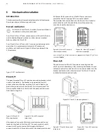
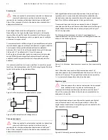
differential between the analog input terminal and common
analog input ground is measured.
Figure 6-20 Vdc input
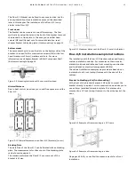
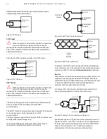
Pt100 input
When connected to a device that resides in a hazardous
area, safety barriers or galvanic isolators may be
required to be interposed between the device and the Spirit
IT
Flow-X flow computer. Refer to the device documentation for
adequate information.
Each Flow-X/M flow module provides two PT100 inputs.
Figure 6-21 PT100 input
HART inputs
When connected to a device that resides in a hazardous
area, safety barriers or galvanic isolators may be
required to be interposed between the device and the Spirit
IT
Flow-X flow computer. Refer to the device documentation for
adequate information.
The first 4 analog input circuits of each Flow-X/M flow module
have an on-board HART modem to facilitate HART
communication.
The Spirit
IT
Flow-X flow computer uses an internal 250
Ω
resistor
for its analog inputs, which is adequate for HART
communication.
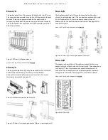
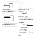
The flow computer supports both a single HART transmitter and
multiple HART transmitter per loop.
If of a single HART device in the loop, the 4-20 mA signal is
measured in parallel and available in the software.
Figure 6-22 HART loop (single transmitter)
Figure 6-23 HART loop (multi-drop)
In systems with HART inputs where a separate external analog
input common is used, it is required to connect the analog input
common and the 0 V with a
47 µF bipolar capacitor
in-between.
Barriers
When devices are located in a hazardous area, safety barriers are
required. For analog inputs, selected MTL Barriers have been
tested with Flow-X/M. Other brands may work as well, but a test
is recommended. Below schematics provide application
examples that have been proved to function.
In all cases, refer to the barrier and device documentation to
ensure proper application of barrier and field wiring.
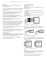
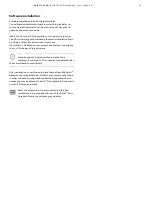
Figure 6-24 Analog 4-20 mA transmitter with barrier
Above figure shows a 4-20 mA transmitter, externally powered.
The barrier is MTL, type 7787+. The Flow-X/M is configured as 1-
5V input, requiring an external precision resistor of 250 Ohm to
convert the 4-20 mA into 1-5 V. If the flow computer is
configured as 4-20 mA, the resistor must be omitted.
Analog input
[1..6]
Analog input
common
0-5 V
source
Pt100
PRT power +
[1..2]
PRT
[1..2]
PRT signal -
[1..2]
PRT power -
[1..2]
(0)4-20 mA
transm.
+
-
24V out
Analog input
signal
Analog input
common
0V
4-20 mA
transm.
Multidrop
+
-
24V out
Analog input
signal
Analog input
common
0V
+
+
+
-
-
-
Analog input
[1..6]
1-5 V
Analog input
common
4-20 mA
transm.
+
-
Analog power +
Analog power -
250
Ω
MTL Barrier
7787+


