1 8
S P I R I T
I T
F L O W - X
I N S T R U C T I O N M A N U A L | I M / F L O W X - E N
6
Electrical installation
Introduction
This chapter provides details on all aspects of the electrical
installation, including field wiring, communication, power supply
and earthing. Since all models use the same Flow-X/M module,
the connection diagrams this chapter apply to all models.
Caution
The Spirit
IT
Flow-X is neither intrinsically safe nor explosion-
proof and can therefore only be used in a designated non-
hazardous (safe) area.
For other devices always refer to documentation supplied by the
manufacturer for details of installation in a hazardous area.
When connected to a device that resides in a hazardous area,
safety barriers or galvanic isolators may be required to be
interposed between the device and the Spirit
IT
Flow-X flow
computer. Refer to the device documentation for adequate
information.
The Spirit
IT
Flow-X modules are fully configurable through
software. No dipswitches or jumpers need to be set inside.
There are no user-replaceable fuses or other components inside.
Opening a module will void any warranty.
For easy reference, the connector details are presented first.
Loop diagrams and additional connection drawings are to be
found below.
Location of connectors
Flow-X/P
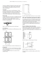
The Flow-X/P flow computer is the panel-mounted version that
has a touch-screen and can contain up to 4 Flow-X/M flow
modules.
The power, I/O and communication terminals are on the back of
the flow computer. The touch-screen module processes the two
RJ45 connectors (for Ethernet) and three 9-pin D-sub male
connectors (for serial communications). These connections are
functional even with no flow module installed. The supported
serial interfaces are
Port
Flow-X/P version 1
Flow-X/P version 2
COM 1
RS232
RS232/RS485
COM 2
RS232/RS485
RS232/RS485
COM 3
RS232/RS485
RS232
Furthermore there are eight 37-pin D-sub female connectors for
the I/O and serial communication ports of the 4 flow modules.
Only the connections for the actual installed flow modules can
be used.
The port connectors are described on page 19.
For the power connection, see page 19.
The 39-pin D-sub connectors are the serial ports of the Display
module. These ports may be used to communicate to devices
such as a gas chromatograph, or a DCS. In Flow-X/P version 1,
Com 1 is RS-232 only, Com 2 and Com 3 may be individually
configured for RS-232 or RS-485. In Flow-X/P version 2, Com 3 is
RS-232 only and Com 1 and Com 2 are configurable. For
connector details, see page 20.
LAN1 and LAN2 are Ethernet connectors, to connect your Flow-
X/P to your network. The modules are used in Multi-module
mode. The individual Ethernet connections of each module are
not used in a Flow-X/P.
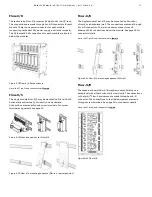
Flow-X/R
The rack-mount Flow-X/R supports up to 8 modules. Each
module has its own set of D-sub 37 connectors (Port A and Port
B). For the pin-out see page 19.
Each module has its own power supply connector, from which it
receives power. At the bottom, 2 Ethernet connections (LAN A
and LAN B) are available for each module. When the modules are
in Multi-Module Mode, only one pair of Ethernet connections will
be used. When the modules are in individual mode, the Ethernet
connections of each individual module are used.
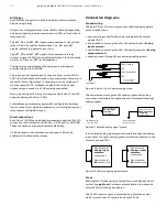
Flow-X/C
The Flow-X/C flow computer is the panel-mounted version that
has a touch-screen and an integral Flow-X/M flow module.
The power, I/O and communication terminals are on the back of
the flow computer. There are two 37-pin D-sub female
connectors for the I/O and two serial ports, supporting RS232
and RS485. Furthermore it has two RJ45 connectors (for
Ethernet) and one 9-pin D-sub male connector, providing a third
serial port that supports RS232 only.
The port connectors are described on page 19.
For the power connection, see page 19.
The 9-pin D-sub connector can be used as a generic serial port to
communicate to devices such as a flow meter, gas
chromatograph or a DCS. The port supports RS-232 only. For
connector details, see page 20.
LAN1 and LAN2 are Ethernet connectors, to connect your Flow-
X/C to your network.
One USB port can be found at the front, which is reserved for
future usage.
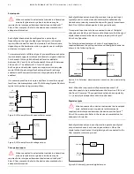
Flow-X/S
The Flow-X/S has room for 1 module. The module is connected
through 2 terminal strips with 39 terminals each. The connection
details for the terminals are listed on page 20.
In addition, the Flow-X/S enclosure has a 24V power connector
and 2 Ethernet connectors (ETH 1 and ETH 2). For the power
connector see page 19.


