S P I R I T
I T
F L O W - X
I N S T R U C T I O N M A N U A L | I M / F L O W X - E N
1 7
Flow-X/R
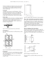
The rack version Flow-X/R requires 8 height units in a 19” rack.
The connections are made through 2 sub-D connectors for each
module. There is one power connector for each module
(supporting redundant 24V power supply, as all other models).
The 2 Ethernet RJ-45 connections for each module are located
below the modules.
Figure 5-18 Flow-X/R Rack enclosure
Note: the 37-pin D-sub connectors are
female
Flow-X/S
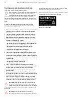
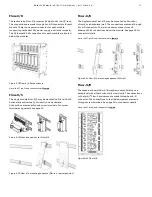
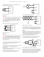
The single module Flow-X/S may be mounted on Din-rail, both
horizontally and vertically, or directly on a backplane.
Connections are made through screw terminals. For screw
terminal assignments see page 20.
Figure 5-19 Mounting options for Flow-X/S
Figure 5-20 Flow-X/S mounting sequence (DIN-rail, vertical position)
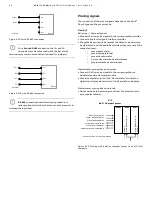
Flow-X/K
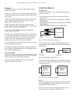
The single module Flow-X/K may be mounted on Din-rail or
directly on a backplane/wall. The connections are made through
2 sub-D connectors. There is one power connector and 2
Ethernet RJ-45 connections below the module. See page 18 for
connector details.
Note: the 37-pin D-sub connectors are
female
Figure 5-21 Flow-X/K mounting sequence (DIN-rail)
Flow-X/B
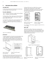
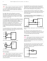
The break-out board Flow-X/B may be mounted directly on a
backplane/wall, either horizontally or vertically. The connections
to the Spirit
IT
Flow-X enclosures are made through a sub-D
connector. The connections to the field equipment are made
through screw terminals. See page 21 for connector details.
Note: the 37-pin D-sub connector is
female
Figure 5-22 Flow-X/B


