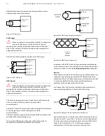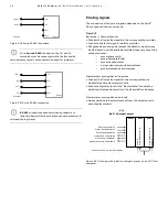
1 4
S P I R I T
I T
F L O W - X
I N S T R U C T I O N M A N U A L | I M / F L O W X - E N
5
Mechanical installation
Introduction
This chapter describes the mechanical aspects of all enclosures.
Drawings contains full drawings with sizes.
Forced ventilation
For Flow-X/P and Flow-X/R models, forced ventilation in
the cabinet is always recommended.
For a Flow-X/R in a 19” rack, please ensure air flow at the front is
not blocked by Ethernet switches or other devices mounted
below or above the Flow-X/R.
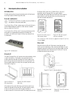
For a Flow-X/R in a 19” rack with 3 or more modules adjacent to
each other it is recommended to install a 19” rackmount
ventilator unit, as shown in Figure 5-1 directly underneath the
X/R enclosure.
Figure 5-1 19” ventilator unit
Flow-X/P
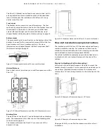
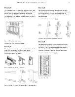
The panel mounted Flow-X/P requires a mounting bracket, which
is part of the delivery. The bracket is designed to allow full
access to the mounted flow modules. This rack is fixed to the
back of the panel in which the Flow-X/P is to be mounted. The
flow computer slides in at the front of the panel, and the screw
fixes the two together.
Figure 5-2 Flow-X/P
Figure 5-3 Flow-X/P mounted
Mounting bracket
(side view)
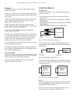
All connectors for power, field wiring and communication are
located at the back of the Flow-X/P. For each module, 2 sub-D
connectors (37-pin) contain all field signals. Additional
connectors exist for 3 the serial ports of the display module, and
2 Ethernet RJ-45 connections. A 24VDC Power connector
completes the lot. See page 18 for connector details.
The modules that are inserted into the Flow-X/P are locked in
place with a bar with the possibility to seal to prevent any
unnoticed unauthorized access.
Figure 5-4 Flow-X/P version 1
rear view (mounted)
Figure 5-5 Flow-X/P version 2
rear view (mounted)
Note: 3 (three) 9-pins D-sub connectors are
male
and the 8 (eight) 37-pin D-sub
connectors
female
Flow-X/C
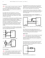
The panel mounted Flow-X/C requires a mounting bracket,
which is part of the delivery. After mounting the bracket to your
cabinet/construction the Flow-X/C can then be slidden into the
bracket and fasten with a knurled screw. The Flow-X/C can be
installed horizontally and vertically.
Figure 5-6 Flow-X/C Mounting bracket
Figure 5-7 Flow-X/C mounted
Figure 5-8. Flow-X/C rear view
(side view)
(mounted)


