bias current
in per unit
Zero-
sequence
diff. current
in per unit
0
1
2
3
4
5
IdMin
Section 1
Operate
conditionally
I
operate
slope = ----------------* 100 %
I
restrain
Sec. 2
Section 3
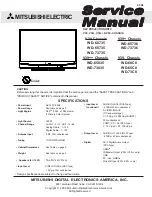
The characteristic
can be moved
up and down
(vertically)
by changing
the setting IdMin
End Section 1
End Section 2
IdMin range: 0.04
–
1.00 IBase
Reset Ratio in all sections:
0.95 (a constant)
Slope 70%
Restrain
Slope 100%
Characteristic if
IdMin = 1.0 pu
IEC98000017-5-en.vsd
D
D
0
1
2
3
4
5
6
IEC98000017-5 V1 EN
Figure 46:
Operate - bias characteristic of the Restricted earth-fault protection, low
impedance REFPDIF (87N)
6.2.7.3
Calculation of differential current and bias current
The differential current (operate current), as a fundamental frequency phasor, is
calculated as (with designations as in figure
0
Idiff = IN + 3I
IECEQUATION2417 V1 EN
(Equation 26)
where:
I
N
current in the power transformer neutral as a fundamental frequency phasor,
3I
0
residual current of the power transformer line (terminal) currents as a phasor.
The bias current is a measure (expressed internally as a true fundamental frequency
current in Amperes) of how difficult the conditions are under which the instrument current
transformers operate. Dependent on the magnitude of the bias current, the corresponding
zone (section) of the operate-bias characteristic is applied, when deciding whether to trip,
or not to trip. In general, the higher the bias current, the higher the differential current
required to produce a trip.
1MRK 502 048-UUS A
Section 6
Differential protection
125
Technical manual