180000044-IEC19000449-1-en.vsdx
Stage 1
Stage 2
V-Setting
U
N
U
t
Delay Delay
V-Setting
IEC19000449 V1 EN-US
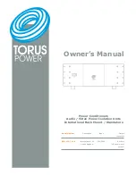
Figure 45: Operating characteristic of a two-stage overvoltage protection
Typical settings:
1st stage:
V-setting
1.15 U
N
Delay
2 s
MaxMin
MAX (1ph)
2nd stage:
V-setting
1.4 U
N
Delay
0.1 s
MaxMin
MAX (1ph)
5.7
Synchrocheck 25 (SYNC)
5.7.1
Mode of operation
GUID-213AD84F-1A1E-4464-BD6F-19471C0152F5 v1
Checking the synchronization criteria (amplitudes, phase-shift and frequency difference) of
two electrical systems and, providing the corresponding limits are satisfied, enabling them to
be connected in parallel.
5.7.2
Features
GUID-77360B06-0E90-4F91-9363-5FA0E9CF3BA9 v1
•
Monitoring synchronism:
Single-phase voltage measurement.
Comparison of the voltages (dU), phase-shift (dPh) and frequencies (df) of two voltage
vectors. Calculation of the corresponding differences between the voltage vectors in the
complex plane.
Evaluation of the fundamental frequency components of the voltage signals (after
filtering of harmonic and DC components).
•
Monitoring voltage:
Section 5
1MRK 505 406-UEN B
Bay protection functions
114
Bay protection functions REB500
Technical manual
© Copyright 2019 ABB. All rights reserved